Bifacial module technology has transitioned from a premium niche to the industry standard. For EPCs and developers, the shift isn’t just about swapping out the panels; it’s about fundamentally rethinking the solar mounting system.
When building a bifacial solar project, you aren’t just harvesting photons from the sky—you are harvesting them from the ground. This “second-side energy” introduces a new set of engineering variables. If your racking system shadows the back of the module, or if your site preparation ignores surface albedo, you are effectively leaving money on the table.
In this guide, we’ll dive into the structural nuances that dictate the success of a bifacial installation and how to make real-world design decisions that protect your LCOE.
Why Bifacial Projects Demand a Shift in Structural Thinking
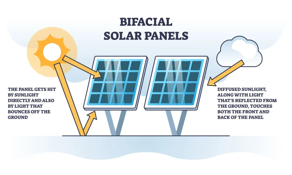
The premise is simple: bifacial modules capture scattered and reflected light on their rear surface. However, the execution is complex. Unlike monofacial projects where the mounting structure is purely a mechanical support, in a bifacial project, the structure is a part of the optical path.
Standard racking designs can inadvertently “strangle” the energy yield. Thick C-channels or poorly placed purlins directly behind the cells create “dead zones.” As engineers, we have to balance structural rigidity (to withstand wind and snow loads) with optical transparency.
The Physics of Albedo: From Snow to Sand
The primary variable for bifacial gain is surface albedo—the measure of solar radiation reflected from the ground. As we’ve seen at SR Solar, albedo isn’t a static number; it’s a site-specific asset.
Understanding the Reflection Spectrum
Before breaking ground, you must assess your environment. Here is a breakdown of common surface albedos we encounter in the field:
| Surface Type | Approximate Albedo (%) | Potential Power Gain |
| Snow | 80% – 85% | 25% – 30%+ |
| Yellow Sand | 20% – 40% | 10% – 15% |
| Cement / Concrete | 20% – 40% | 8% – 12% |
| Dry Land | 20% – 23% | 7% – 10% |
| Grass | 15% – 25% | 5% – 8% |
| Water Surface | 5% – 12% | < 5% |
Engineering Insight: On flat roofs, we’ve found that simply painting the surface white or laying high-reflectivity waterproofing membranes can boost power generation by over 10%. It’s often the highest ROI “tweak” you can make in an urban C&I project.
Critical Structural Factors for Minimizing Rear-Side Shading
When building a bifacial solar project, the mounting structure must be “invisible” to the rear side as much as possible.
1. The “5cm Rule” for Purlins
A common mistake in EPC projects is using wide purlins that sit flush against the module frame. This creates a linear shadow that significantly reduces the efficiency of the back-side cells.
SR Solar Engineering Tip: We recommend that the purlin or any structural cross-member be at least 5cm away from the back of the module. This allows diffuse light to “wrap around” the obstruction and hit the cells.
2. Avoiding Component Shading
It’s not just the steel that causes problems. String inverters, combiner boxes, and thick cable bundles are often mounted directly behind modules for convenience. In a bifacial setup, this is a design flaw.
- Cabling: Use specialized cable clips to route wires along the frame or the vertical posts.
- Inverters: Mount them at the end of rows or in the shade of the mounting posts, rather than directly under the modules.
3. Height Matters
The higher the mounting system, the better the uniformity of the light hitting the back side. While raising the height increases wind load and steel costs (CAPEX), it significantly improves bifacial gain. Our team usually performs a sensitivity analysis to find the “sweet spot” where the increased yield outweighs the extra steel cost.
How to Choose the Right Solar Mounting System
Choosing a mounting system isn’t just about the lowest price per watt; it’s about the application environment.
1. Ground Mount (Utility-Scale)
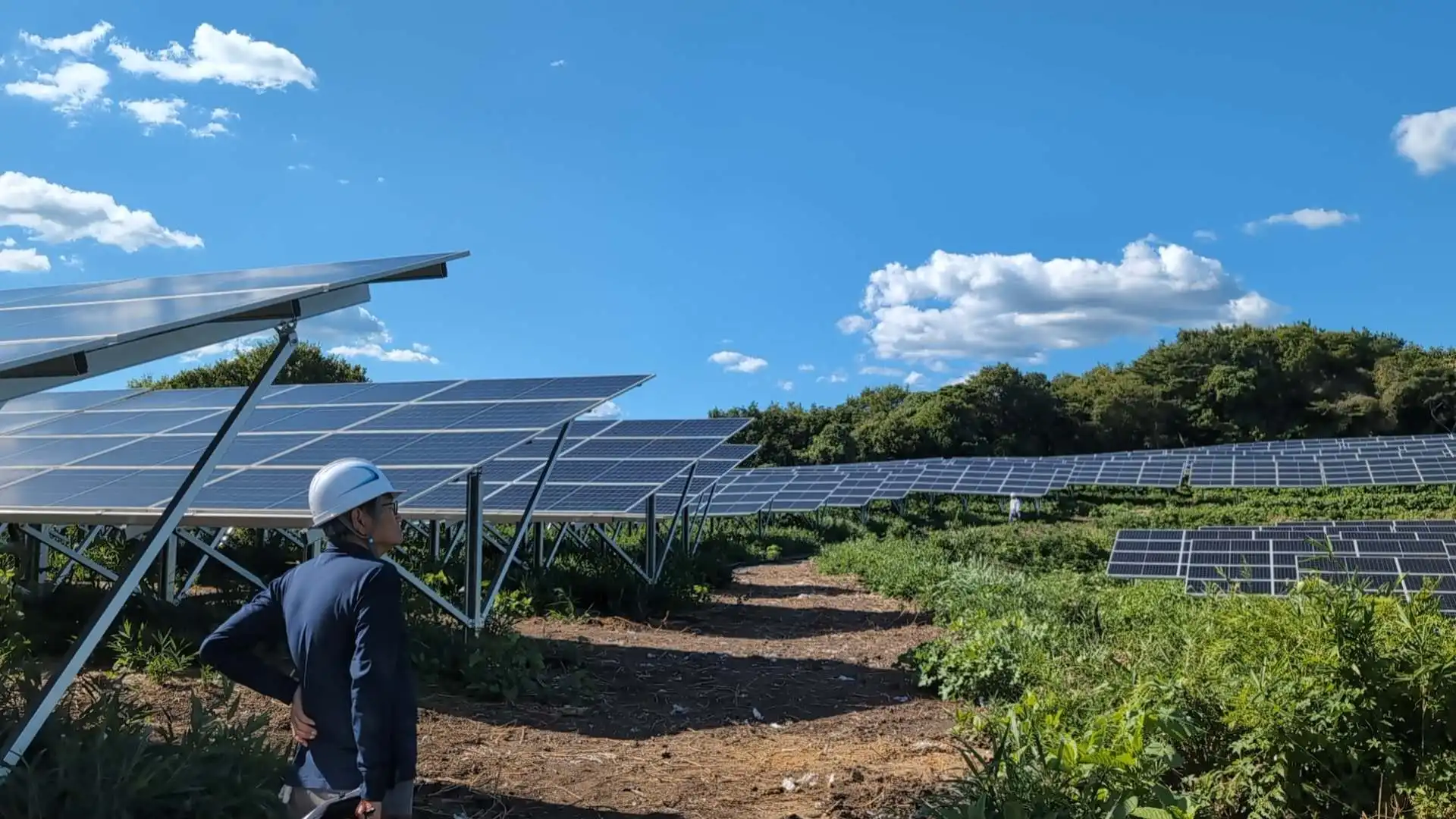
For large-scale projects on dry land or sand, a fixed-tilt system with an optimized ground clearance (usually 1 meter or higher) is the standard. If the budget allows, a 1P or 2P Single-Axis Tracker is even better, as it minimizes the structural footprint directly behind the module.
2. Rooftop Mount (C&I)
On concrete flat roofs, use a tilt-up racking system rather than a flush mount. This allows the back side to breathe and catch reflections from the roof surface.
- Tip: Check the roof’s load-bearing capacity before increasing the tilt angle, as this increases the ballast required.
3. Agri-PV and Carports
These are the “gold mines” for bifacial modules. Because the modules are mounted high off the ground (to allow for farming or cars), the rear-side light capture is maximized. At SR Solar, we design specialized long-span structures for carports that eliminate mid-module shading entirely.
Real-World Experience Layer: Insights from the Field
In our experience at SR Solar, we’ve seen projects where the theoretical bifacial gain was 15%, but the actual yield was only 8%. Why?
- Dust Accumulation: In desert environments (Yellow Sand), dust accumulates on the back side of modules. Developers often forget to include rear-side cleaning in their O&M budgets.
- Vegetation Management: In “Grass” environments, if the weeds grow too high, they don’t just shade the front; they kill the reflection for the back.
- The “Shadow of the Frame”: We’ve worked on several utility-scale installations where we had to redesign the clamping system because the standard clamps were casting “hard shadows” on the rear cells, leading to localized hotspots.
The Economic Impact: CAPEX vs. Bifacial Yield
Building a bifacial solar project involves a delicate balance between upfront costs and Levelized Cost of Energy (LCOE).
- Steel Volume: Raising the structure height by 30cm might increase your steel weight by 5-8%.
- Labor Efficiency: A more complex “bifacial-friendly” racking system might take 10% longer to install.
- The Payoff: If that extra steel and labor result in a 10% annual yield increase over 25 years, the ROI is undeniable.
At SR Solar, we provide our clients with a structural-optical analysis. We don’t just sell you steel; we help you calculate if the extra height or the specific purlin spacing will actually pay for itself in your specific geography.
Decision-Making Section: How to Choose the Right Solar Mounting System
Before you finalize your procurement, ask your engineering team these four questions:
- What is the Ground Albedo? (If it’s below 15%, maybe stick to monofacial or go for the cheapest racking).
- Does the Purlin Design Block the Rear Cells? (Demand a 5cm+ clearance).
- What is the Wind Load Profile? (Higher mounting heights mean higher torque on the foundations).
- Is the ROI based on “Lab Conditions” or “Field Reality”? (Factor in soil, dust, and maintenance).
Conclusion: Future-Proofing Your Bifacial Asset
Bifacial technology is a powerful tool for lowering LCOE, but it requires an “engineering-first” approach to mounting. A solar park is only as efficient as its weakest link—don’t let that link be a poorly designed bracket that shades your investment.
By focusing on ground reflectivity, structural clearance, and smart component placement, you can ensure your bifacial project delivers on its promise of superior energy density.
Ready to optimize your next bifacial project? At SR Solar, we specialize in engineering mounting solutions that maximize rear-side gains without compromising structural integrity. Whether you are dealing with high-wind coastal zones or high-albedo desert sites, our team is here to provide a design validation for your project.
[Contact SR Solar for a Technical Consultation]
Summary
The success of a bifacial solar project hinges on the synergy between the module and its mounting structure. This article explored the critical role of surface albedo, the necessity of minimizing rear-side shading through smart purlin design (the 5cm rule), and the commercial trade-offs between CAPEX and long-term yield. Engineers must look beyond simple support to see the racking system as an integral part of the plant’s optical performance.
FAQs
- Does bifacial gain work on all types of ground? While it works everywhere, the gain is most significant on high-albedo surfaces like snow, sand, or white-painted roofs. On dark soil or water, the gain is minimal (often under 5%).
- How much height should I add to my mounting system for bifacial modules? Generally, a ground clearance of 0.8m to 1.2m is the “sweet spot.” Beyond 1.5m, the marginal gain in light uniformity often doesn’t justify the increased steel cost and wind risk.
- Can I use standard trackers for bifacial modules? Yes, but “bifacial-optimized” trackers are better. They feature narrower torque tubes or offset mounts to ensure the tube doesn’t cast a shadow directly down the center of the module.
- Is it worth painting a roof white for a bifacial project? In most C&I projects, yes. A high-reflectivity TPO membrane or white coating can increase energy production by 10-15%, often paying for itself within 2-3 years.
- How does SR Solar handle rear-side shading in its designs? We utilize specialized purlin profiles and mounting clips that ensure a minimum gap between the module and the structure, and we provide layout simulations to minimize self-shading.