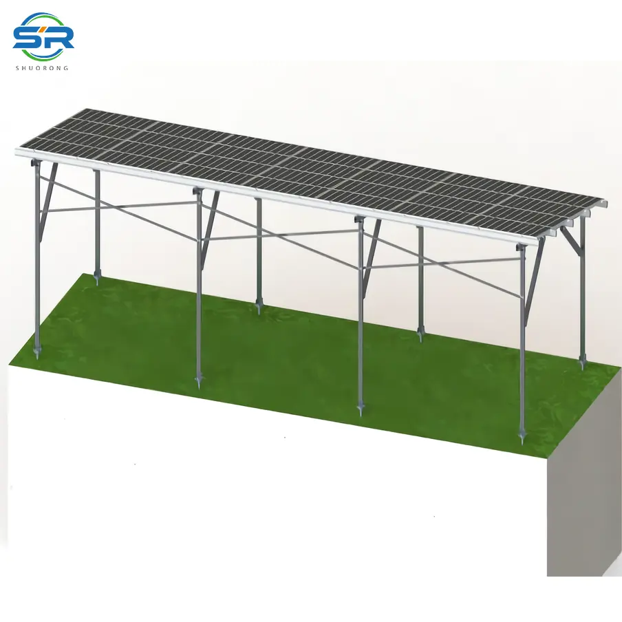
While driven piles and concrete Ballasted systems have their place, the ground screw foundation for ground mount has shifted from an alternative solution to an industry standard for challenging terrains. But why is this the case? How do you determine if a site is genuinely “ground screw territory,” and how do you navigate the engineering nuances of different blade configurations?
Let’s bypass the marketing gloss and dissect the actual mechanics, terrain limitations, and economic realities of ground screw integration from a peer-to-peer structural perspective.
1. Decoding the Ground Screw Foundation for Ground Mount: What It Is and How It Holds
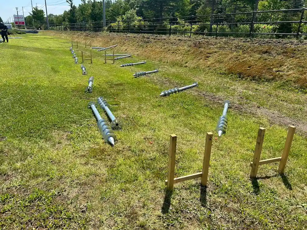
At its core, a solar ground screw is a continuous piece of steel pipe—typically manufactured from Q235B or Q355B steel and treated with a heavy hot-dip galvanized (HDP) layer or Zinc-Aluminum-Magnesium (ZAM) coating—featuring welded helical blades at its lower section.
Unlike a traditional driven pile that relies purely on skin friction between the soil and the smooth steel profile, a ground screw acts as a massive mechanical anchor.
The Mechanics of Load Transfer
When a solar array faces high wind loads, the mounting system experiences massive uplift forces (tension) and downward forces (compression). How does the ground screw handle this?
- Uplift Resistance (Tension): The helical blades anchor themselves beneath the soil wedge. To pull the screw out, the wind force must overcome not just the skin friction of the shaft, but the shear strength of the entire cone of soil sitting above the helical blades.
- Downward Load Bearing (Compression): The load is transferred down the shaft and distributed across the surface area of the spirals into deeper, more consolidated soil strata, minimizing the risk of uneven settlement.
From an engineering standard perspective, high-quality ground screws are designed and tested to comply with international codes such as AS/NZS 1170 (structural design actions for Australia) and JIS C 8955 (load seismic design for solar arrays in Japan).
High-Water Tables and Cohesionless Soils (Sandy Terrains)
In coastal areas or sandy deserts, driven piles often fail because the soil lacks the cohesion to create sufficient skin friction. Every time the ramming rig strikes, the sand liquefies slightly and shifts. Ground screws, by contrast, compress the surrounding soil laterally as they are threaded in, increasing local soil density and securing a firm hold even in loose, cohesionless matrices.
Undulating Hills and Mountainous Slopes
When a project site looks like a rolling landscape rather than a flat desert, civil site preparation (grading) can decimate your budget. If you use driven piles on a slope, you face variable embedment depths, requiring custom post lengths or extensive cutting and punching on-site.
Ground screws mitigate this. They can be installed at varying depths into the natural slope while maintaining a consistent height for the flange or top connection, completely eliminating the need for expensive land terracing.
Soft Clay and Agricultural Land
In soft alluvial clays, a driven pile needs to go incredibly deep—sometimes past 4 to 5 meters—to find stable friction. A ground screw utilizes its wide spiral blades to engage a large volume of the upper, stiffer soil crust, achieving the required pull-out resistance at a significantly shallower embedment depth (typically 1.6 to 2.1 meters).
A Common Error in the Field: > We frequently see EPCs assuming that ground screws are completely incompatible with rocky soils. In our project experience across fractured limestone and cobble-rich terrains, we found that by introducing a pre-drilling step (using a continuous-flight auger or down-the-hole hammer to create a pilot hole slightly smaller than the pipe diameter), ground screws could still be installed reliably. The screw threads then bite into the fractured rock face, achieving pull-out values that no driven pile could ever match.
3. Head-to-Head: Ground Screws vs. Alternative Foundations
To justify the engineering choices to stakeholders, we must look at how ground screws stack up against the two primary competitors: Concrete Foundations and Driven (Rammed) Piles.
| Engineering & Logistical Parameters | Ground Screw Foundations | Driven / Rammed Steel Piles | Concrete Ballast / Bored Piers |
| Installation Speed per Rig | High (Approx. 150–200 units/day) | Very High (Approx. 250–300 units/day) | Low (Requires curing time, formwork) |
| Heavy Machinery Dependency | Low/Medium (Rotary hydraulic drives) | High (Heavy tracking ramming rigs) | High (Concrete mixers, excavators) |
| Tolerance to Subsurface Rocks | High (With optional pre-drilling) | Low (Refusal or pile deformation occurs) | High (Excavation bypasses rocks) |
| Immediate Load Bearing | Yes (Ready for racking instantly) | Yes (Ready instantly) | No (Requires 7 to 28 days of curing) |
| Environmental Impact & Remediation | Excellent (100% removable & recyclable) | Excellent (Removable) | Poor (Massive carbon footprint, permanent ground scarring) |
| Civil Site Prep Cost (Grading) | Minimal (Adapts to topography) | Low/Medium | High (Requires level ground) |
Why Not Just Concrete?
Concrete requires water on-site, mixing, pouring, rebar placement, and days—if not weeks—of curing time. If your project is in a remote, arid region, the logistics of hauling water and concrete mixers can ruin your LCOE. Ground screws are dry operations; the moment the hydraulic drive unsnaps from the screw flange, your installation crew can begin mounting the aluminum or ZAM racking structure.
Why Not Just Driven Piles?
Driven piles are highly efficient on flat, stone-free agricultural land. However, if the pile strikes a large boulder mid-way down, it either bends, veers off-vertical alignment, or hits “refusal” before reaching target depth.
When a driven pile hits refusal, you are left with an unaligned structural element. When a ground screw encounters minor obstructions, its pointed tip and corkscrew action can often displace small rocks laterally.
Each foundation has its own advantages, but each foundation is suitable for different terrain conditions, and the decision still needs to be made based on the geological survey report.
1. Standard Continuous-Thread Ground Screws
- Design: Features a continuous helical thread wrapping around the lower 1/3 to 1/2 of the pipe shaft, usually with a narrow pitch.
- Best Suited For: Uniform, cohesive soils, stiff clays, and gravelly sands.
- Mechanics: The continuous thread acts like a wood screw, cutting smoothly into the soil matrix without destroying the surrounding soil structure, preserving natural lateral compaction.

2. Twin-Blade Ground Screws
- Design: Features two distinct, wider helical blades welded at spaced intervals near the tip of the pile.
- Best Suited For: Medium-to-loose sands and softer silt layers.
- Mechanics: In low-cohesion soils, you need more surface area perpendicular to the uplift force. The twin blades act as dual deadman anchors. The spacing between the two blades is precision-engineered so that the failure shear plane of the bottom blade does not overlap with the top blade, effectively doubling the pull-out resistance without increasing the entire pipe length.
3. Multi-Blade Ground Screws
- Design: Utilizes three to four expansive, large-diameter helical plates stacked vertically on the lower shaft.
- Best Suited For: Ultra-soft alluvial soils, mudflats, or organic peat layers.
- Mechanics: When the soil has almost zero shear strength, the foundation must rely entirely on end-bearing capacity. These massive plates behave like underground snowshoes, spreading the downward structural weight across a wide horizontal footprint and trapping large columns of soil to counteract extreme wind-uplift events.

4. Adjustable Ground Screws
- Design: Features either an adjustable internal sleeve, a multi-slotted top flange, or a threaded neck connection that allows for post-installation height and angular corrections.
- Best Suited For: High-precision trackers or extreme mountain terrains with highly variable localized slopes.
- Mechanics: In utility-scale tracker projects, structural tolerances are razor-thin (often less than ±5mm variation along the torque tube axis). If a ground screw is driven slightly off-plumb due to underground gravel shifting, an adjustable head allows the installation team to correct the alignment, pitch, and height up to 50 mm -100mm without pulling out the foundation.

5. The Economic Impact on LCOE: A Business Case for EPCs
When evaluating foundation costs, looking solely at the per-unit purchase price of the steel is a fundamental engineering oversight. The foundation dictates your downstream labor and equipment rental burn rates.
Minimizing Civil Works and Land Remediation
Massive earth-moving, grading, and compacting operations can account for a significant chunk of early-stage CAPEX. Because ground screws can absorb topographical variances, you can leave the natural drainage and vegetation intact. This not only slashes civil costs but simplifies environmental permitting with local authorities.
Optimizing Crew Hours (The “Man-Minutes Per Watt” Metric)
A standard 3-man crew operating an excavator-mounted hydraulic rotary drive can easily install 150 to 200 ground screws in an 8-hour shift. Since there is zero curing wait time, the mechanical installation team can follow immediately behind. This parallel workflow shortens the high-risk mobilization phase of construction, reducing the interest-during-construction (IDC) metric for the project developer.
Corrosion Resistance & Structural Longevity
Corrosion Resistance & Structural LongevityAt SR Solar, we emphasize that the structural integrity of a ground screw must match the 25-to-30-year operational lifespan of modern N-type PV modules. By applying a hot-dip galvanization coating thickness that exceeds standard requirements (often >85μm according to ISO 1461), or by engineering ZAM coated structural variants, we ensure that the structural loss due to underground soil corrosion remains well within safe margins over three decades.
6. Engineering Summary & Technical FAQ
Summary Matrix
Ground screws represent a highly adaptable, zero-concrete, rapid-deployment foundation alternative that bridges the gap between difficult geotechnics and cost-effective construction. By matching the correct blade geometry (Continuous, Twin, Multi) to your site’s specific soil pull-out testing data, EPCs can eliminate structural failure risks while optimizing field labor efficiency.
Technical FAQs
Q1: What happens if a ground screw hits a large underground boulder during rotation?
A: If it’s a minor rock, the screw’s pointed tip and continuous torque will often push it aside. However, if it hits a massive boulder causing a torque spike, the operator must stop immediately to prevent structural deformation of the steel shaft. The standard procedure is to reverse the screw, pre-drill a pilot hole using a rock-drilling auger to fracture the obstruction, and then reinstall the screw into the same location.
Q2: How do you verify that a ground screw meets the specified uplift requirement on-site?
A: You cannot rely solely on theoretical calculations. An on-site Pull-Out Test (Static Load Tension Test) must be performed. A hydraulic jack apparatus is mounted over a newly installed screw, and a tensile load is applied up to 1.5 – 2 the design wind load, measuring displacement over time to ensure it complies with local structural codes.
Q3: Can ground screws be used in highly acidic or corrosive soils?
A: Yes, but soil resistivity and pH testing are critical during the geotechnical survey. In aggressive soils (pH < 4.5 or resistivity < 1000 Ω-cm), standard galvanization might degrade prematurely. In these scenarios, we specify thicker hot-dip galvanization (100 μm), transition to advanced ZAM coatings, or increase the structural steel wall thickness (sacrificial steel allowance) to ensure code compliance over 25 years.
Q4: How does the installation torque correlate to the holding capacity of the screw?
A: There is a direct empirical correlation between installation torque and soil bearing capacity. As the screw penetrates denser soil strata, the torque required to rotate it increases. By monitoring the hydraulic pressure gauge on the drive head, operators can estimate whether the screw has reached a soil layer capable of delivering the required pull-out and compressive resistance.
Q5: Are ground screws reusable if a solar farm is decommissioned?
A: This is one of their greatest advantages. Unlike concrete piers that must be blasted out or left in the ground as environmental waste, ground screws can be put into reverse rotation and cleanly extracted from the soil. The site can immediately return to its original agricultural or natural state, and the steel piles can be 100% recycled or repurposed.
Need Engineering Clarification for Your Next Site?
Every site features a unique geological fingerprint. If you are currently evaluating a challenging terrain or looking at soil report data trying to balance pile depth versus blade configurations, contact the SR Solar structural team for a comprehensive foundation engineering consultation and localized structural analysis.