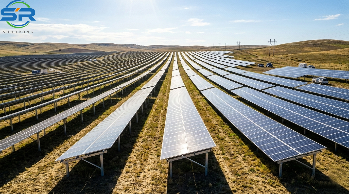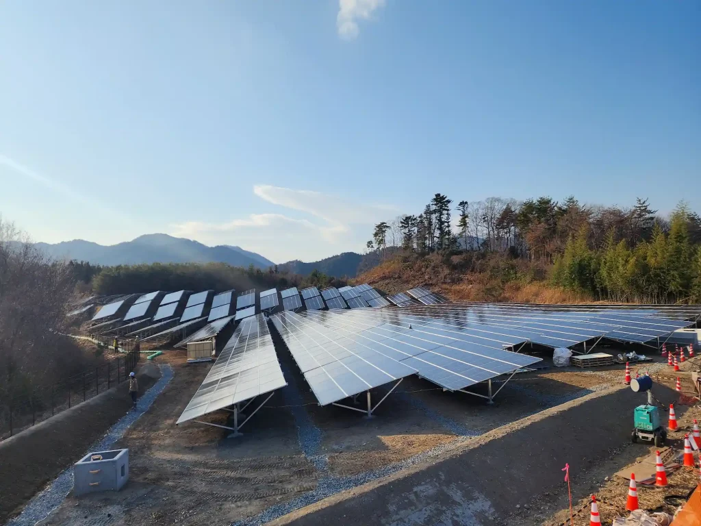
Designing a ground-mounted solar system involves more than selecting a mounting structure and arranging solar panels. Ground solar mounting structural design and configuration must take into account project location, environmental loads, module specifications, soil conditions, foundation requirements, installation methods, and the customer’s specific requirements.
Two solar projects may use the same photovoltaic modules and have similar capacities, yet require different mounting structures because their terrain, wind conditions, soil properties, installation height, or construction requirements are different.
So, how is a ground solar mounting structure designed? What information is required before engineering begins? And how can the structural configuration be adjusted to suit a particular project?
Understanding these questions helps customers make better decisions, avoid unnecessary design changes, and obtain a mounting solution that is suitable for both the project requirements and on-site installation.
1. What Determines the Design of a Ground Solar Mounting System?
A ground solar mounting system is designed around the conditions of the actual project rather than a fixed structural configuration. Several factors influence the final design.
Project Location and Environmental Conditions
The geographical location of the project is one of the starting points for structural design. Environmental conditions determine the loads that the mounting structure needs to withstand throughout its service life.
Important considerations include:
- Wind speed and wind load
- Snow load, where applicable
- Terrain and site conditions
- Corrosion exposure
- Local building and structural design requirements
Wind and snow loads can significantly affect the required member dimensions, support spacing, bracing arrangement, connections, and foundation design. A structure designed for one location should not automatically be used at another without checking the relevant conditions.
When project-specific load data is available, it can be provided for engineering assessment. If not, the design team can evaluate the environmental conditions based on the project location, applicable standards, and available meteorological information.
Solar Module Specifications
Solar modules are another important part of the structural design. Their dimensions, weight, mounting positions, and arrangement directly influence the supporting structure.
The engineering team needs to consider:
- Module length and width
- Module weight
- Mounting hole positions
- Clamp zones and mounting requirements
- Portrait or landscape orientation
- Number of modules per row
Changing the module size or arrangement may require adjustments to the rails, purlins, beams, support spacing, or connections. Even if the overall project capacity remains unchanged, a different module layout can result in a different structural configuration.
Site Conditions and Project Requirements
The physical site and the customer’s requirements also influence the design.
For example, ground clearance may need to accommodate vegetation, equipment, maintenance activities, or specific site conditions. The required tilt angle, row spacing, installation method, and available construction equipment may also affect the final structure.
A mounting solution should therefore be evaluated as a complete system rather than selected based on one parameter alone.
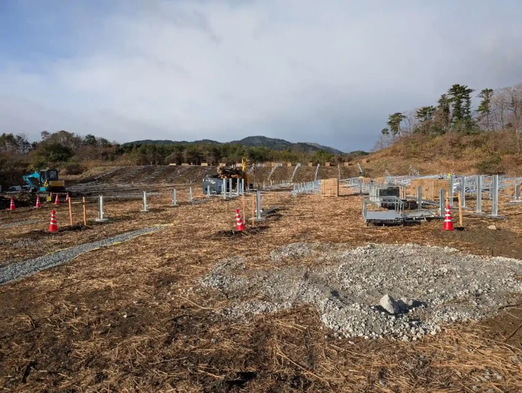
2. What Information Is Required for Ground Solar Mounting Design?
Customers do not always have a complete structural design when they first contact a mounting system supplier. Some have detailed drawings, while others have only the project location, capacity, and module specifications.
The more project information available at the beginning, the easier it is to evaluate the structure accurately and reduce unnecessary revisions. However, an initial discussion can still begin with basic information, and missing details can be clarified as the project develops.
Basic Project Information
The following information is useful for an initial assessment:
- Project location or geographical coordinates
- Project capacity or module quantity
- Project layout, if available
- Module specifications or datasheet
- Preferred mounting structure configuration
- Required tilt angle and ground clearance
- Applicable design standards
- Special project requirements
If the customer already has a preliminary design, drawings can also be provided for review and optimization.
Wind and Snow Load Information
Wind and snow loads are important inputs for structural design. If the project has specified wind speed, wind pressure, snow load, or other environmental design parameters, these should be shared with the engineering team.
If the customer does not have this information, the engineering team can assess the relevant conditions based on the project location, applicable design standards, and available meteorological data.
This helps establish the environmental conditions used in the structural design instead of relying on assumptions that may not be appropriate for the project.
Geotechnical Investigation Report
For ground-mounted solar projects, a geotechnical investigation report is particularly important because it provides information about the ground conditions and supports foundation selection.
Depending on the investigation scope, the report may include:
- Soil classification and composition
- Soil layers and ground conditions
- Bearing capacity or relevant soil resistance data
- Groundwater conditions
- Geotechnical recommendations
The more detailed the report, the better the engineering team can evaluate the foundation requirements.
Without sufficient soil information, foundation selection and design may require additional assumptions or further investigation. This is why we recommend providing the geotechnical report whenever it is available.
Applicable Standards and Special Requirements
Different projects may require different structural design standards, such as ASCE, Eurocode, JIS, or AS/NZS.
If the project specifies a particular standard, customers should communicate this clearly at the beginning. The design approach and structural verification will be based on the applicable requirements and agreed project scope.
Other requirements, such as preferred materials, construction restrictions, equipment limitations, or specific structural arrangements, should also be discussed before the design is finalized.
3. How Does SR Solar Develop a Ground Solar Mounting Structure Design?
Ground solar mounting design is a process in which project information is gradually translated into a structural solution. At SR Solar, the engineering process considers the overall mounting system rather than treating individual components as isolated parts.
Step 1: Evaluate Project Conditions and Environmental Loads
The first step is to understand the project location, environmental conditions, module requirements, and design criteria.
Wind and snow loads are reviewed based on the information supplied by the customer or assessed using the project location, applicable standards, and available environmental data.
This information establishes the design conditions that influence the structural configuration and subsequent engineering verification.
Step 2: Determine the Structural Layout
Once the basic project conditions are understood, the structural layout can be developed.
This includes determining the module arrangement, number of panels supported by each structure, orientation, support positions, row spacing, and other relevant layout parameters.
The layout needs to work with the project requirements while remaining practical for manufacturing, transportation, and installation.
Step 3: Determine Structural Dimensions and Configuration
The engineering team then evaluates the main structural parameters, including:
- Span and support spacing
- Beam and rail dimensions
- Post spacing
- Structural height
- Ground clearance
- Bracing arrangement
- Connection configurations
These parameters are interconnected. Increasing the span, changing the installation height, or adjusting the module arrangement may affect the loads carried by structural members and the requirements for other components.
For this reason, structural configuration is not simply a matter of changing one dimension. The related parts of the structure need to be reviewed together.
Step 4: Perform Overall Structural Verification
The mounting structure needs to be evaluated as a complete system.
Depending on the configuration, structural verification includes the relevant posts, beams, purlins or rails, bracing members, connections, fasteners, and interfaces between components.
The purpose is to assess whether the complete structure meets the applicable design requirements under the specified project conditions.
A common mistake in project planning is to focus only on the dimensions or strength of the main beams while overlooking the connections, supporting members, or foundation interfaces. A mounting system works as an integrated structure, and its performance depends on how all the components work together.
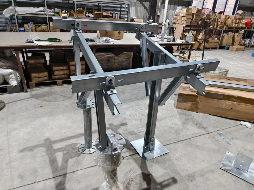
4. How Is the Ground Solar Mounting Structural Configuration Determined?
Structural configuration defines how the mounting system is arranged and how its components work together to support the solar modules.
The configuration can be adjusted according to project conditions, but changes must be evaluated from an engineering perspective.
Module Arrangement and Structural Layout
The number of modules per row, orientation, mounting arrangement, and overall project layout influence the structural design.
The configuration should accommodate the module dimensions and mounting requirements while considering the support positions and practical installation sequence.
Span and Support Spacing
Span and support spacing are important factors in determining the structural member dimensions and overall configuration.
A longer span may reduce the number of supports required in some layouts, but it can also increase the structural demands on beams, rails, connections, and other members. A shorter span may require more supports while potentially allowing different member sizes.
The most suitable arrangement depends on the structural requirements, material selection, foundation conditions, and overall project cost. There is no universal span that works best for every ground-mounted solar system.
Tilt Angle and Ground Clearance
Tilt angle and structural height can be adjusted according to the project requirements.
The engineering team needs to consider the module arrangement, environmental loads, ground conditions, installation requirements, and the resulting structural configuration.
If the customer requires a specific height or tilt angle, this information should be provided during the initial design stage whenever possible. Changes made later may affect multiple structural parameters and require additional engineering review.
Customized Structural Configurations
Almost all major configuration parameters can be adjusted within the limits of engineering feasibility.
Customers may specify a preferred structure, ask SR Solar to optimize an existing concept, or provide project information for a new design.
However, customization does not mean every requested dimension or configuration can be adopted without review. Structural performance, applicable standards, manufacturing feasibility, and installation conditions must remain part of the design decision.
5. How to Select the Right Foundation for a Ground Solar Mounting System?
The foundation transfers the loads from the mounting structure to the ground. Its selection is closely related to soil conditions, structural loads, site constraints, and installation methods.
There is no single foundation type suitable for every ground-mounted solar project.
Concrete Foundation
Concrete foundations may be used when the project conditions, structural requirements, and construction methods make them suitable.
Depending on the design, concrete foundations may involve cast-in-place construction, concrete footings, or other foundation configurations. The connection between the mounting structure and the concrete foundation also needs to be considered.
Where ground conditions or structural requirements call for additional measures, foundation dimensions or reinforcement may need to be adjusted.
Driven Pile Foundation
Driven pile foundations use steel piles installed into the ground with suitable construction equipment.
Depending on project requirements, different pile profiles may be considered, including U-shaped, C-shaped, H-shaped, or other customized sections.
The suitability of a driven pile depends on the ground conditions, design loads, required embedment, installation equipment, and site constraints.
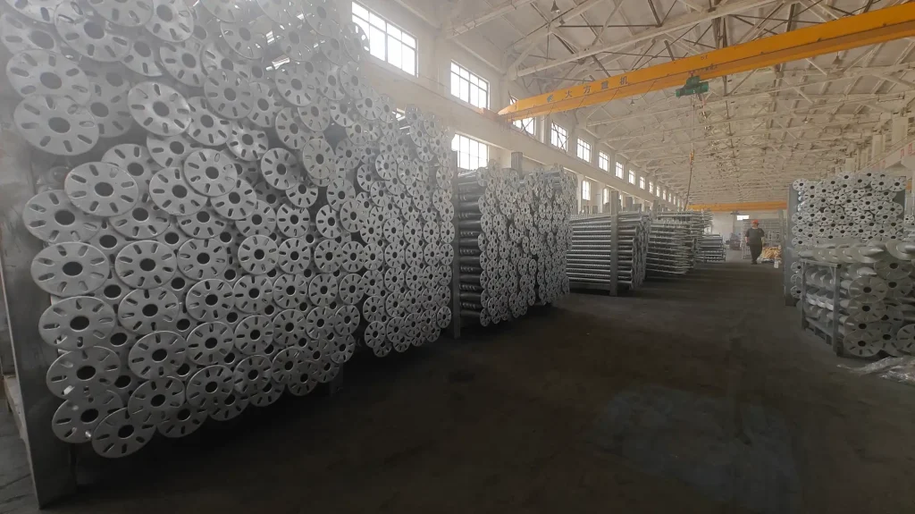
Ground Screw Foundation
Ground screws provide another foundation option for ground-mounted solar structures.
Different lengths, diameters, blade configurations, and connection arrangements can be selected according to project conditions. Standard or customized ground screws may be considered depending on the requirements.
Their suitability needs to be evaluated based on soil conditions, loading requirements, installation feasibility, and relevant project specifications.
Why Geotechnical Conditions Matter
A common EPC error is to select a foundation based on a previous project without confirming whether the soil conditions are comparable.
Two sites may appear similar on the surface but have different soil layers, resistance characteristics, or groundwater conditions. These differences can affect foundation selection and installation requirements.
In our project experience, having detailed geotechnical information available at an early stage makes foundation evaluation more practical and helps avoid unnecessary changes during project development.
If a customer has a preferred foundation type, SR Solar can evaluate it against the available project information. If the proposed option is not suitable, we will explain the considerations and recommend an alternative where appropriate.
6. Material Selection: Aluminum vs. Steel for Ground Solar Structures
Material selection affects structural performance, weight, corrosion protection, manufacturing, installation, and project cost. Aluminum and steel are both widely used in solar mounting structures, but they have different characteristics and should be selected according to the design requirements.
Aluminum Structures – AL6005-T6
AL6005-T6 aluminum alloy is used in solar mounting structures where lightweight components and corrosion resistance are important considerations.
Typical characteristics include:
- Lightweight components for easier handling
- Anodized surface treatment
- Corrosion resistance
- Potential advantages in component handling and preassembly
Aluminum generally has lower stiffness than steel, so member dimensions and structural configuration may need to be carefully designed, particularly when longer spans are required.
Aluminum structures may offer installation advantages, but their suitability depends on the required span, loads, section design, and project budget.
Steel Structures – S350GD
S350GD steel is commonly used in solar mounting structures where structural requirements and material cost need to be balanced.
Steel generally offers higher stiffness and strength characteristics than aluminum in typical structural applications, depending on the selected section and design.
Steel mounting structures may use different corrosion protection options, including hot-dip galvanizing (HDG) and ZAM-coated steel.
ZAM-coated steel is steel with a zinc-aluminum-magnesium coating applied during the steel manufacturing process. Its corrosion protection characteristics make it an option for mounting structure components, subject to the project environment and design requirements.
Foundation Materials and Accessories
Other materials may be used in different parts of the mounting system.
For example:
- Q235B or Q355B steel for applicable foundation components
- Aluminum for rails and selected mounting components
- Steel for structural members and connections
- SUS304 stainless steel for applicable fasteners or accessories
The material selection should be based on component function rather than applying the same material to every part of the system.
How Should the Material Be Selected?
Material selection should consider more than the unit price.
The engineering team needs to evaluate the required structural performance, member dimensions, span, corrosion environment, manufacturing process, transportation, installation, and project cost.
For some projects, aluminum may be a suitable option. For others, steel may provide a more practical balance of structural requirements and cost.
Different material options can be evaluated and quoted where appropriate, but changing material is not always a direct substitution. The structural configuration may need to be reviewed again to ensure that the alternative material remains suitable.
7. Structural Design Is Also About Installation Efficiency and Project Cost
A mounting structure can meet its structural requirements and still be difficult or inefficient to install. Practical installation considerations should therefore be included during the design process rather than left entirely to the construction stage.
Designing for Easier Installation
The arrangement of components, connection methods, and assembly sequence can affect how quickly a structure is installed.
Where feasible, the design may consider:
- Simplified connection arrangements
- Practical assembly sequences
- Reduced unnecessary components
- Factory preassembly
- Clear coordination between structural members
These considerations can make the structure easier to handle and assemble on site.
Considering Labor and Site Conditions
Installation efficiency is influenced by the available construction equipment, site access, ground conditions, workforce experience, and installation sequence.
A design that requires excessive adjustment or complicated assembly may increase labor requirements. Considering installation conditions at the beginning can help reduce unnecessary work and make the construction process more practical.
Balancing Material and Installation Costs
The lowest material cost does not necessarily result in the lowest total project cost.
For example, a structure with a lower material cost may require more supports, more connections, additional on-site work, or a more complicated installation process.
When evaluating a mounting solution, it is useful to consider the complete picture:
- Structural requirements
- Material cost
- Manufacturing feasibility
- Transportation and packaging
- Installation labor
- Site efficiency
The goal is not simply to minimize the amount of steel or aluminum used, but to develop a structure that meets project requirements while remaining practical to manufacture, transport, and install.
8. From Initial Design to Final Quotation: How SR Solar Works with Customers
Every project starts from a different point. Some customers already have complete structural drawings, some have a preliminary concept, and others only have basic project information.
SR Solar supports these different situations through three approaches.
Design According to Customer Drawings
If the customer already has completed structural drawings and defined requirements, SR Solar can work according to the provided design and project specifications.
The drawings and requirements are reviewed to establish the scope of the solution and coordinate the relevant mounting structure details.
Engineering Optimization of an Existing Design
If the customer has a preliminary design but wants to improve the structure, SR Solar can evaluate the existing concept.
Possible considerations include structural configuration, material selection, component arrangement, manufacturing feasibility, installation requirements, and cost.
The objective is to improve the practicality of the solution without overlooking the project’s structural requirements.
Custom Design Based on Project Information
Customers do not need to have a completed mounting structure design before contacting us.
If the project information is available, SR Solar can develop a structural configuration based on the project location, module specifications, environmental conditions, foundation requirements, applicable standards, and other relevant information.
This allows customers to discuss the project with our engineering team even when the structural arrangement has not yet been finalized.
Design Revisions and Engineering Review
Project requirements may change during the design process. Module dimensions, row layout, tilt angle, structural height, material selection, or foundation requirements may be adjusted.
In our engineering practice, design changes are not treated as simple drawing revisions. When the structural configuration changes, the relevant parts of the design are reviewed again to verify that the updated solution remains suitable for the project requirements.
This helps ensure that the final design is based on the confirmed project conditions rather than outdated assumptions.
What Does the Customer Receive?
After the design and quotation process, the main project deliverables generally include:
- Project quotation
- Structural design drawings
- Bill of Materials (BOM)
The specific scope depends on the project requirements and the agreed quotation.
Throughout the process, customers can communicate their requirements, review the proposed solution, and discuss feasible adjustments with the engineering team.
9. A Ground Solar Mounting Design Should Start with the Project
Ground solar mounting structural design is not about selecting a standard structure and applying it to every site. It is about understanding the project conditions and developing a configuration that meets the relevant structural, environmental, installation, and cost requirements.
The most important factors include project location, wind and snow loads, module specifications, structural layout, foundation conditions, material selection, corrosion protection, and construction requirements.
A complete project design also requires communication. Providing accurate project information at an early stage helps engineers evaluate the structure more effectively, while reviewing design changes ensures that the updated solution remains consistent with the project requirements.
Whether you already have structural drawings, a preliminary concept, or only basic project information, SR Solar can work with you to evaluate the requirements, develop a suitable mounting structure configuration, and provide a project-specific solution.
The goal is not simply to supply mounting components. It is to help you obtain a structural solution that is practical, properly evaluated, and suitable for the conditions of your solar project.
FAQs
1. What information is required for ground solar mounting system design?
Basic information includes the project location, module specifications, project capacity or module quantity, layout requirements, applicable design standards, wind and snow loads, and geotechnical information. Not every detail must be available at the initial inquiry stage, but more complete information helps improve design accuracy.
2. Can SR Solar design a ground solar mounting system from scratch?
Yes. Customers can provide basic project information without having a completed structural design. SR Solar can develop a mounting structure configuration based on the project conditions, module requirements, environmental loads, foundation conditions, and applicable standards.
3. Why is a geotechnical report important for ground-mounted solar projects?
A geotechnical report provides information about soil composition, soil layers, ground conditions, and relevant soil resistance characteristics. These details help engineers evaluate the foundation type and design requirements. A more detailed report generally supports a more informed foundation assessment.
4. Which foundation is best for a ground-mounted solar mounting system?
There is no single foundation type that is best for every project. Concrete foundations, driven piles, and ground screws may all be suitable under different conditions. The selection depends on soil conditions, structural loads, site restrictions, construction equipment, and project requirements.
5. Can ground solar mounting structures be customized?
Yes. Structural height, span, support spacing, tilt angle, module layout, materials, foundation arrangements, and other configuration details may be customized. However, each change needs to be evaluated against structural requirements, manufacturing feasibility, installation conditions, and applicable standards.