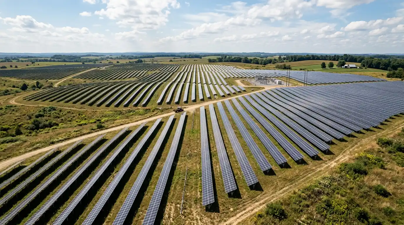
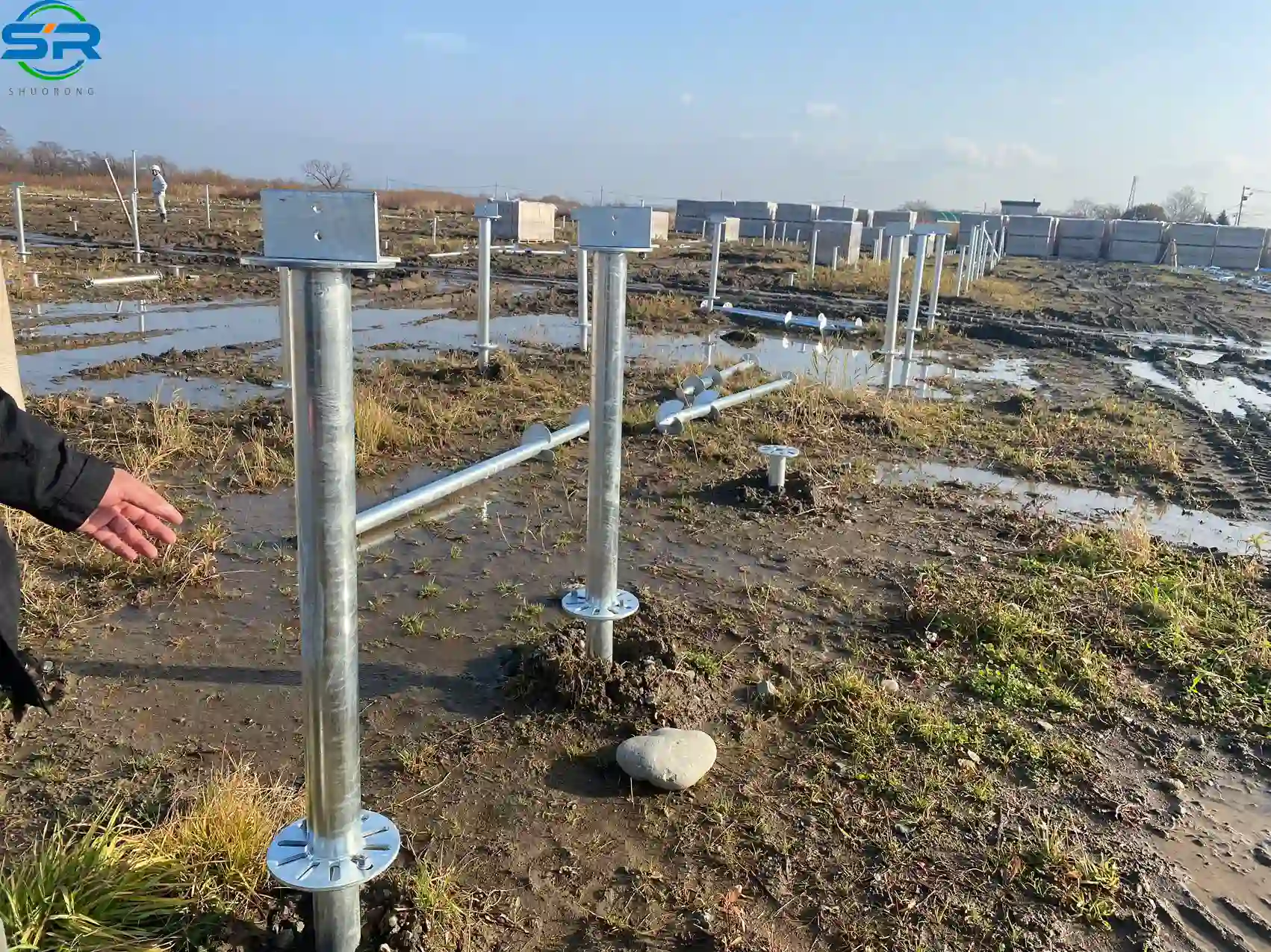
For utility-scale solar installations, solar ground screws have shifted from an alternative foundation method to an industry standard for mitigating complex subsurface risks. In modern ground-mounted arrays, the structural foundation is the single most critical asset protection layer, yet it is often the most mismanaged. When engineering procurement teams face tightening project timelines, unpredictable soil cohesion, and aggressive wind shear, selecting the correct ground-anchoring methodology directly dictates the project’s internal rate of return (IRR) and long-term asset liability. This guide provides a peer-to-peer structural analysis of screw foundation mechanics, field installation realities, and the material science required to secure a 25-year operational lifespan.
1. Geotechnical Foundation Selection Matrix for EPC Contractors
Choosing a sub-grade anchor is not a matter of catalog shopping; it is a balance of soil mechanics and civil asset management. The table below outlines the core engineering trade-offs between competing foundational methods under real-world utility project conditions.
| Engineering Metrics | Solar Ground Screws | Driven Piles (C/H-Channel) | Concrete Foundations |
| Primary Load-Bearing Mechanism | Continuous friction + continuous thread mechanical interlock | Skin friction + horizontal soil passive pressure | Dead-weight gravity + basal bearing capacity |
| Typical Installation Time | 30 to 60 seconds per unit | 45 to 90 seconds per unit | Days (Excavation, pouring, curing) |
| Hard/Rocky Soil Adaptation | Excellent (via pre-drilling without pile distortion) | Poor (High risk of pile head buckling or refusal) | Excellent (But cost-prohibitive due to extensive blasting) |
| Immediate Load Readiness | 100% (Instant racking assembly allowed) | 100% (Instant racking assembly allowed) | 0% (Requires 7 to 14 days of concrete curing) |
| Environmental Remediation | 100% reversible (Clean extraction, zero residue) | High remediation effort (Soil compaction/voids left behind) | Zero reversibility (Requires heavy demolition/blasting) |
| Frost Heave Resistance | High (Continuous blade anchors below the frost line) | Moderate (Susceptible to jacking forces on smooth shafts) | High (If poured entirely below frost depth) |
2. Mechanical Load-Bearing Profiles & Sub-Grade Soil Dynamics
How do solar ground screws manage to deliver massive pull-out resistance without the dead weight of concrete? The answer lies in soil mechanics. When a smooth-shaft driven pile is pushed into the earth, it relies entirely on the lateral friction between the soil particles and the steel surface. If the soil becomes saturated, or if wind-induced dynamic fluttering vibrates the racking system, this skin friction can degrade rapidly.
A continuous-thread or multi-flange ground screw changes the stress distribution entirely. As the screw is mechanically driven into the ground, its spiral blades cut through the soil, compacting the surrounding earth instead of displacing it upward. This creates a localized zone of high-density soil wrapped tightly around the core pipe.
When upward tension (pull-out force) or downward compression is applied, the load is transferred through the helical flanges into the soil profile. To pull the screw out, the wind load must physically lift a solid cone of soil resting above each blade layer. In typical medium-dense clay or sandy loam, a properly sized 76mm diameter screw with a 2mm thread pitch can comfortably achieve vertical tensile and compressive capacities exceeding 175 kN, alongside horizontal shear limits of up to 60 kN.
Matching Geological Profiles to Screw Geometry
EPCs often make the mistake of treating ground screws as a one-size-fits-all commodity. Soil profiles dictate your geometric configurations:
- Cohesive Clays and Silts: Ideal for continuous-thread small-diameter screws. The clay molds into the screw threads, maximizing long-term lateral stability.
- Loose Sands and Gravels: Require wide, localized helical flanges (often multi-blade designs). The broad surface area acts as an underground anchor plate, using the weight of the upper sand layers to counteract aggressive uplift forces.
- Hardpan and Caliche: Best approached with heavy-wall, fine-threaded designs. A smaller pitch prevents the screw from stalling during high-torque mechanical installation.
3. Structural Material Science & Long-Term Corrosion Mitigation
Deep underground, your foundations face a silent enemy: electrochemical corrosion. Soil moisture, pH fluctuations, and localized oxygen pockets create a highly reactive environment that can eat through structural steel, compromising your utility-scale array long before its 25-year power purchase agreement (PPA) expires.
The Standard: Batch Hot-Dip Galvanizing (ISO 1461)
A common EPC error is accepting pre-galvanized steel tube components that are subsequently welded and modified. The heat from welding destroys the zinc layer precisely at the critical junction points—such as where the spiral flange meets the core tube.
At SR Solar, we enforce a strict batch hot-dip galvanizing process strictly compliant with ISO 1461 and ASTM A123 standards. The entire steel assembly is fabricated, welded, and then completely submerged into a molten zinc bath.

For structural steel with a wall thickness between 3mm and 6mm, this guarantees an average zinc coating thickness of at least 70 μm (microns). For heavy-duty variants exceeding 6mm thickness, the coating minimum jumps to 85 μm. In typical non-aggressive soils, the zinc consumption rate ranges from 1 to 2 μm per year, meaning an 85 μm layer provides a massive safety buffer for several decades of operational life.
Surviving the Mechanical Friction of Installation
Will the zinc scrape off during installation? It is a valid engineering concern. The hot-dip process doesn’t just apply a superficial paint layer; it forms a metallurgical bond consisting of distinct zinc-iron alloy layers that are actually harder than the base steel itself. This rugged outer armor resists abrasions from rocks and gravel during the high-torque rotational driving process, leaving the deep-seated corrosion protection fully intact once the screw reaches its target depth.
4. The “Real-World” Layer: Hard Engineering Lessons from the Field
Step away from the clean engineering software models for a moment. What actually happens when your construction crew hits the field?
The Rocky Ground Refusal Myth
A major misconception among inexperienced solar installers is that solar ground screws cannot be deployed in rocky soils or areas littered with boulders. They assume driven piles are superior because they can simply be rammed harder. In reality, ramming a C-channel pile into an underground boulder results in structural buckling, twisting, or pile head destruction—requiring immediate extraction and expensive remediation.
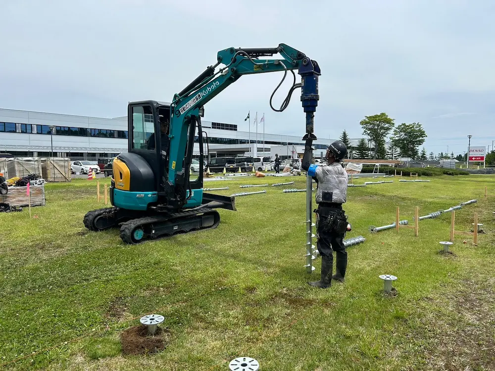
How experienced EPCs handle rocky terrain: They utilize a combination of pre-drilling and targeted screw installation. By deploying a hydraulic down-the-hole (DTH) pneumatic hammer or auger drill ahead of the pile-driving rig, a precise pilot hole is excavated through the stone layer. The ground screw is then driven directly into this pre-drilled pathway. The spiral threads cut into the micro-fractures of the rock, delivering anchoring values that far surpass what could ever be achieved in loose dirt.
A Common EPC Error: Mismanaging the Structural Tolerance
If your ground screws are installed out of alignment, your mechanical tracking systems or rigid fixed racking will not fit. Forcing a racking system onto misaligned foundations introduces massive structural pre-stress. This can warp tracking bearings, stall tracking motors, or cause micro-cracking across the solar modules during heavy wind events.
Field-Proven Guidelines for Construction Crews:
- Enforce Pre-Drilling Adjustments: If an underground obstruction shifts the screw off-center during the first few turns, back it out immediately. Do not attempt to force-bend the screw sideways with the machine arm.
- Continuous Vertical Monitoring: Equip your hydraulic power heads with digital dual-axis inclinometers. The vertical deviation must never exceed 1% of the total pile length.
- Horizontal Spatial Tolerances: The center-point of the screw head must remain within ±20 mm of the engineering layout coordinates.
5. Economic Hard Data: Driving Down EPC LCOE
Every hour your installation crew spends on-site adds directly to your balance sheet via heavy machinery rentals, labor wages, and overhead. Let us look at how choosing solar ground screws shifts the financial equation in a typical 50MW utility-scale project requiring roughly 15,000 foundational anchor points.
Civil Works Compression
Traditional concrete piers require a multi-stage construction line: land clearing, heavy excavation, structural formwork setup, rebar tying, concrete mixing/transport, pouring, and a non-negotiable 7 to 14-day curing window. If a sudden rainstorm hits, the open trenches flood, ruining the soil compaction and delaying the schedule indefinitely.
With high-torque hydraulic ground screw rigs, a single machine with a two-person crew can cleanly install between 200 to 300 screws per day. There is zero soil extraction, zero concrete mud to manage, and absolute zero curing time. The moment the power head detaches from the screw flange, your racking crew can follow right behind, fastening the steel columns and aluminum rails. This slashes total civil mobilization timelines by up to 40%, insulating the project from unpredictable weather liabilities.
Environmental Decommissioning and Land Reclamation Cost Reduction
Many modern land leases for solar farms carry strict “return-to-greenfield” clauses. If you pour thousands of tons of concrete into arable farmland or protected desert zones, you are looking at millions of dollars in future decommissioning expenses to blast, excavate, and haul away that concrete. Ground screws can simply be reversed out of the ground via the same hydraulic rigs, leaving the topsoil undisturbed and saving massive backend capital.
6. Engineering Standards and Global Compliance
For a utility-scale project to secure institutional financing, every structural component must be backed by rigorous calculations that satisfy localized building codes. We do not design based on guesswork; we engineer to recognized global standards.
- AS/NZS 1170 (Australia/New Zealand): Essential for determining dynamic wind load combinations, especially when designing for high-velocity wind zones (Cyclonic Regions C and D). Ground screws must prove they can withstand extreme cyclical lifting forces.
- JIS C 8955 (Japan): A highly conservative standard focusing on strict soil bearing capacities and seismic loading characteristics. Our structural calculations map the exact thread pitch to the verified soil cohesion factors outlined in this code.
- Eurocode 3 & Eurocode 7: Governing structural steel design and geotechnical engineering across Europe, demanding clear calculations on pile skin friction degradation over extended periods.
By adhering strictly to these engineering parameters, SR Solar ensures that your mounting system foundations pass third-party bankability audits without friction, allowing swift financial closure for project developers.
7. Technical Consultation and Project Support
Selecting the right foundational layout requires deep synthesis of geotechnical data, environmental load factors, and structural geometry. Don’t leave your project’s primary anchor point to a standard catalog guess.
Contact the SR Solar structural engineering division today for a comprehensive review of your upcoming project’s Geotechnical Report. We provide optimized pile depth mapping, customized alloy coatings, and precise structural calculations tailored to your exact wind and snow loads.
8. Frequently Asked Questions (FAQs)
Q1: How do solar ground screws perform in regions prone to heavy frost heave?
In cold climates, moisture in the upper soil layers freezes and expands, exerting a massive upward “jacking” force on buried structures. If you use a smooth pile, this frost heave can slowly lift the foundation out of the ground year after year. Solar ground screws defeat this by placing their heavy continuous threads deep below the local frost line. The frozen upper soil slips past the smooth upper pipe, while the deep, un-frozen soil holds the threaded anchor firmly down, preventing vertical displacement.
Q2: What happens if a ground screw strikes a massive underground boulder that cannot be drilled?
If an impenetrable obstruction or solid bedrock ledge is struck close to the surface, the standard procedure is to relocate the pile position slightly along the east-west axis, provided it remains within the structural tolerance of the racking system’s main beam. If relocation is impossible, the screw is extracted, the hole is pre-drilled using a heavy-duty rock-shattering DTH hammer, or a localized concrete anchor block is cast specifically for that single node.
Q3: Can ground screws be used on steep hillside terrains?
Yes, this is actually one of their premier application scenarios. Traditional concrete or standard ramming piles require extensive terracing and land leveling to allow machinery to operate safely, which severely disrupts the natural topography and water drainage. Hydraulic screw rigs can operate on significant slopes. By adjusting the installation depth and leaving varying lengths of the screw pipe extended above ground level, a perfectly flat, laser-leveled plane can be achieved for the racking system without altering the hillside contour.
Q4: How is the actual load capacity of an installed screw verified on a live project site?
Before mass production and installation begin, we perform static Pull-out Tests (Proof Loading) directly on-site. A hydraulic jack framework is attached to an installed sample screw, and real-time tension is applied up to the engineering design limit (e.g., 1.5 times the calculated worst-case wind lift). Dial gauges measure the microscopic movement of the pile. The screw passes only if the vertical displacement remains well within strict structural tolerances under full load.
Q5: What is the difference between Q235B and Q355B steel for ground screw production?
Q235B and Q355B represent different carbon steel grades. Q235B has a yield strength of 235 MPa and is widely used for standard, cost-effective ground screw projects with moderate load requirements. Q355B features a much higher yield strength of 355 MPa. We specify Q355B for high-torque installations, heavy wind zones, or extra-long screws (above 3000mm) where the pipe wall must resist intense rotational torsional stress without twisting or deforming.