The catastrophic failure of a peer project within the industry has sent shockwaves through the solar community, serving as a harsh reminder of the hidden risks in solar mounting system design. For Engineering, Procurement, and Construction contractors, a localized structural collapse does not just mean lost components. It triggers a cascading financial disaster that impacts the Levelized Cost of Energy, destroys investor confidence, and can completely void asset insurance. Why do seemingly solid metal structures fail? How can an experienced project manager identify engineering blind spots before the pile drivers arrive on site? As utility-scale installations scale into increasingly challenging environments, understanding the physical and operational weak points of solar mounting system design becomes a critical baseline for project bankability.
1. Decision-Oriented Outline
To help EPC project managers navigate structural liabilities, this technical analysis breaks down the systemic failure points across the project life cycle, from early subsurface analysis to final field execution.
Analyzing the risks of insufficient soil investigation, incorrect cohesion assumptions, and frost line oversights. The financial impact includes unexpected foundation shifting, expensive field rework, and structural failure of driven piles.
Analyzing installation deviations, short-driven piles, excessive verticality offsets, and improper fastener torque. The financial impact includes localized frame buckling, increased on-site labor overhead, and shortened mechanical lifespan.
Analyzing the dangers of supplier material downgrades, gauge reduction, steel grade substitution, and thin galvanization layers. The financial impact includes accelerated red rust corrosion, structural failure under wind or snow loads, and total asset write-downs.
Analyzing the engineering boundary limits between manageable fluid dynamics and true Force Majeure events. The financial impact includes catastrophic structural collapse, system baseline warranty invalidation, and legal liability disputes.
Introducing our vertically integrated approach, covering site-specific engineering, professional soil report verification, wind tunnel data matching, and end-to-end quality control from our own production factory. The financial impact includes optimized material weight efficiency, minimized field installation hours, and guaranteed 25-year structural reliability
2. Foundation Errors and Flawed Geotechnical Reports in Solar Mounting System Design
Why do some ground-mounted arrays begin to tilt, warp, or suffer from severe localized settlement within the first two years of grid connection? In our project experience, the root cause rarely originates in the visible upper metal framework. It is almost always buried deep in the subsurface layers. A common EPC error is treating a preliminary soil investigation as a simple, administrative box-checking exercise rather than the absolute baseline of all solar mounting system design. When a project developer tries to compress the pre-construction schedule or reduce initial capital expenditure by skimping on soil boreholes or skipping field pull-out tests, they force their engineering partners to calculate structural margins in the dark.
When subsequent layout calculations are performed using a flawed or incomplete geotechnical report, every downstream milestone in solar mounting system design is fundamentally compromised. Ground-driven piles rely entirely on exact soil parameters to resist heavy lateral wind loads and vertical dead loads. Engineers must evaluate soil cohesion metrics, internal friction angles, and seasonal moisture variations to determine how much friction the metal surface can generate against the ground. These calculations must align with strict international safety standards, including the American Society of Civil Engineers guidelines under ASCE 7, the Japanese JIS C 8955 standard, and the European Eurocode standard EN 1991.
If the geotechnical assessment assumes a uniform, medium-dense sand layer, but the project site actually features highly expansive clay or an unmapped shallow water table, the structural design fails before manufacturing even begins. What happens when the frost line is completely ignored in cold-climate regions? As moisture within the upper soil layers freezes during winter, it expands and exerts massive upward vertical forces against the steel. If the pile embedment depth was not designed to extend deep past this active frost boundary, the soil grips the pile and slowly lifts it out of the ground. When the foundations shift by even a few inches across a single block, the upper racking twists. This creates severe structural stresses that lead to micro-cracks in the solar cells, shattered module glass, broken string connections, and a completely broken solar asset.
3. Construction Deviations and Field Quality Controls in Solar Mounting System Design
Let us assume the structural blueprints are mathematically perfect. The calculations clear local wind speed requirements with comfortable margins, and the technical drawings represent a highly optimized solar mounting system design. Yet, during the mechanical installation phase on-site, the project can still transform into a massive liability if field quality control slips. In our project experience, construction deviations are rarely driven by intentional negligence. Instead, they are caused by tight EPC timelines, a lack of specialized training for mechanical installation crews, and unexpected subsurface obstacles.
The most critical field execution errors usually involve driven piles stopping short of their designed depth. During high-speed ramming, the pile driver operator hits a hidden boulder, a hard caliche layer, or an unmapped rock shelf. Instead of pausing the operation to deploy a specialized pre-drilling rig, the field crew often stops driving because the pile feels structurally solid. This leaves the pile sitting high above its designed embedment depth. From an engineering perspective, this increases the lever arm of the wind-loaded solar array while severely reducing the soil skin friction keeping the pile anchored. When a heavy storm hits the site, the overturning safety margin drops far below safe limits, violating the original intentions of the solar mounting system design.
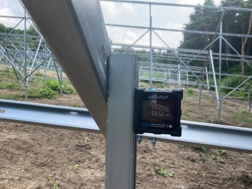
Another severe issue is verticality deviation and pile misalignment. Vertical steel columns are dimensioned to transfer heavy loads straight down to the earth. When a pile is driven with an alignment error exceeding one degree from absolute vertical, it introduces an unintended eccentric bending moment. This lateral stress forces the structural members to handle massive twisting forces they were never configured to resist under standards like ASCE 7 or JIS C 8955.
Combine this with field crews tightening structural fasteners via uncalibrated impact wrenches, and you create a system where bolts are under-torqued. Under continuous seasonal wind vibrations, these loose connections gradually back out, causing structural joints to fail and the racking sections to come apart. How can a project maintain its integrity when the physical build deviates so far from the engineering intent?
4. The Cost-Cutting Trap: Non-Professional Suppliers and Material Skimping
In an ultra-competitive global utility-scale market, the pressure on EPC contractors to minimize Balance of System costs is intense. However, selecting a solar mounting vendor solely based on the lowest price per watt is a high-risk gamble. Non-professional suppliers routinely protect their thin profit margins by quietly cutting down material specifications, a practice that fundamentally violates the principles of a safe solar mounting system design. The real danger here is that these material downgrades are completely invisible to the naked eye on the day of mechanical completion. The system looks perfect when you take the drone photos for the handover ceremony, but the structural deficiencies hide in silence until an extreme storm or heavy snow event arrives to expose them.
Consider the severe impact of gauge reduction. If the engineered solar mounting system design requires a 3.0mm C-channel steel profile to resist heavy winter snow accumulation, but the supplier delivers a 2.5mm variant to save money, that seemingly small 0.5mm reduction strips away a massive percentage of the profile’s structural bending resistance. Under a major snow load, the steel channels will experience localized buckling, leading to a sudden collapse of the entire row.
Material grade substitution is another hidden trap that undermines solar mounting system design. Shifting from high-strength carbon steel like Q355 to a standard commercial grade like Q235 represents a massive drop in yield strength. When a peak wind load sweeps across the solar farm, a structure built with downgraded steel will cross its elastic limit and undergo permanent plastic deformation. The frame warps permanently, twisting the modules and ruining the system layout.
Furthermore, insufficient anti-corrosion coating can ruin a project in a few short years. If a supplier delivers a hot-dip galvanized layer that measures only 45 microns instead of the specified 80 microns, the protective zinc coating will be consumed rapidly in aggressive environments like agricultural zones or high-salinity coastal areas. Within three to five years, widespread red rust forms along critical structural connections. The steel thins out due to oxidation, and the overall load capacity of the mounting system experiences a massive drop, failing to meet the long-term durability metrics established by EN 1991. Finally, shortening the actual length of the driven pile to save raw steel directly robs the project of its anchoring depth, leaving the solar farm highly vulnerable to complete pull-out failure during severe wind events.
5. Force Majeure and Beyond-Code Environmental Pressures on Solar Mounting System Design
In rare instances, every single pre-construction step is executed flawlessly. The geotechnical survey is deep and thorough, the engineering layout complies strictly with local building regulations, the field construction matches the tolerances, and the raw materials are fully up to specification. Yet, the solar farm still suffers extensive damage. When an unprecedented environmental event breaks all historical statistical records, the disaster falls under legal and structural Force Majeure. For example, if a project site is struck by a major category 5 typhoon with sustained wind velocities that far exceed the design boundaries of local meteorological codes, the sheer kinetic energy of the moving air can tear entire solar blocks right off the ground.
However, a professional EPC must be able to distinguish between an unavoidable act of nature and a structural engineering failure hidden behind the excuse of Force Majeure. This distinction is where a highly sophisticated solar mounting system design proves its bankability. Solar arrays behave exactly like large airplane wings anchored to the earth. As high-speed wind flows across the tilted panels, it creates alternating vortices on the leeward side of the structure. If the frequency of this vortex shedding matches the natural frequency of the mounting framework, a destructive harmonic event known as torsional fluttering occurs.
Many non-professional mounting suppliers only calculate static wind pressure from a standard handbook. They completely ignore dynamic fluid mechanics and harmonic vibrations, failing to execute a comprehensive solar mounting system design. When an entire solar array collapses under a wind gust that was well below the legal design speed limit, the supplier will quickly blame the weather, but an experienced structural engineer can look at the twisted steel and instantly identify a fatal design flaw. By matching engineering to standards like ASCE 7, JIS C 8955, and EN 1991, structural engineers can build safety margins that keep the system standing when standard designs fail.
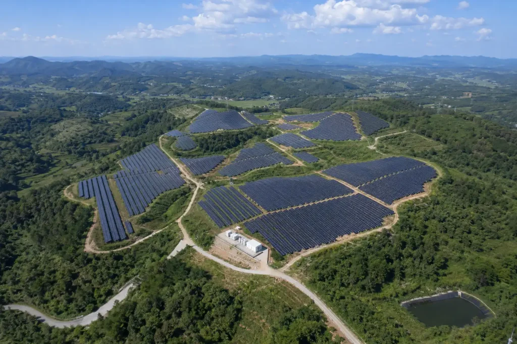
6. The SR Solar Engineering Standard: Eliminating Structural Risk in Solar Mounting System Design
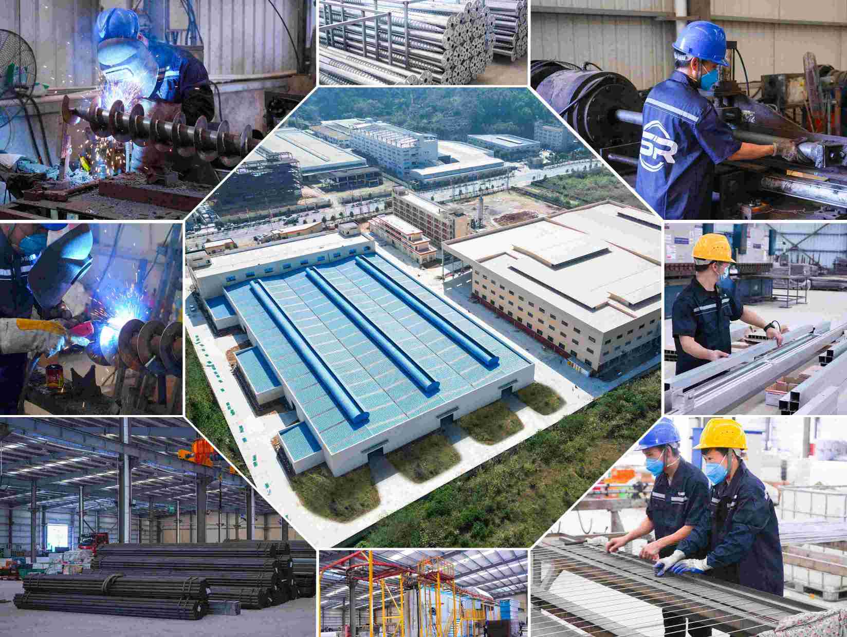
At SR Solar, we do not view solar mounting systems as simple metal commodities to be stamped out and shipped. We treat them as critical, load-bearing infrastructure engineered to protect your multi-million-dollar power generation assets for over 25 years. Operating our own integrated manufacturing plant alongside an experienced, technical export team, we maintain absolute control over the entire engineering, material sourcing, and production cycle. We eliminate guesswork by applying strict engineering standards to every phase of solar mounting system design.
Site-Specific Structural Engineering
We never utilize generic, one-size-fits-all product templates. Every single project configuration we deliver is custom-engineered to the exact GPS coordinates and terrain topography of your site. Whether your project is located in a coastal zone exposed to high-velocity marine winds or an alpine ridge facing severe snow loads, our engineering team performs independent structural simulations to optimize profile geometries, ensuring a perfect balance between material cost-efficiency and absolute safety in our solar mounting system design.
Geotechnical Evaluation and Adaptation
We do not design blindly. Once you provide our team with your site’s raw geotechnical reports and pile pull-out test data, our internal structural engineers deeply analyze the soil profile. We calculate precise skin friction limits and corrosivity metrics to determine the exact pile embedment depth required for your project. If the site features challenging subsurface conditions like solid granite or loose sand, we adapt our solar mounting system design instantly, shifting to pre-drilled concrete foundations or optimized heavy ground screws to keep your project anchored.
Wind Tunnel Validated Design
Our engineering methodologies are rooted in real-world fluid dynamics instead of handbook approximations. We shape our designs using empirical data derived from extensive wind tunnel testing on representative solar array profiles. By accurately mapping dynamic wind pressure distributions and vortex behavior, our engineers eliminate the risk of torsional fluttering, ensuring your solar arrays remain stable even in regions prone to sudden wind gusts, perfectly matching the intents of a wind-resilient solar mounting system design.
Strict Material Traceability
We completely eliminate the risk of unannounced material downgrades. Every batch of steel, high-strength carbon steel, premium aluminum alloy, and advanced Zinc-Aluminum-Magnesium coated steel entering our manufacturing facility must possess comprehensive Mill Test Certificates. We strictly guarantee that the chemical composition, yield strengths, and overall mechanical performance of the delivered components match your approved engineering blueprints exactly, upholding the safety margins of our solar mounting system design.
Quality Control Throughout Production
Owning our manufacturing plant gives us total quality assurance control that trading companies simply cannot match. From tracking profile thickness during automated roll-forming to monitoring precision punching tolerances and executing rigorous hot-dip galvanizing layer thickness checks, our quality control runs through every phase of production. Every component delivered to your field site is factory-inspected, ensuring an error-free, seamless installation process that reduces your construction labor costs and validates our integrated solar mounting system design.
7. Technical Conclusion and Frequently Asked Questions
While the racking and mounting infrastructure typically accounts for less than 30 percent of a solar project’s initial CAPEX, a structural failure results in a 100 percent loss of generation capacity and catastrophic financial exposure. Mitigating this risk requires an engineering-first mindset throughout the lifecycle of solar mounting system design. By conducting thorough pre-construction soil evaluations, enforcing tight field quality controls, and partnering with a vertically integrated manufacturer that controls its own production lines, EPC contractors can reliably lower their Levelized Cost of Energy and lock in project returns for the next 25 years.
Solar Mounting Structural FAQ
Q1: Why is the choice of raw materials so critical for a long-term solar mounting system design? The choice of raw materials dictates both the yield strength and corrosion resistance of the structure. For example, using high-strength carbon steel like Q355 provides a minimum yield strength of 355 MPa, allowing engineers to design lighter profiles that carry much higher structural loads compared to standard commercial steel like Q235, which has a yield strength of only 235 MPa. Substituting lower grades into an optimized solar mounting system design reduces load capacity by over 33 percent, risking structural failure under heavy wind or snow.
Q2: What are the main structural benefits of using Zinc-Aluminum-Magnesium coatings over standard hot-dip galvanizing? Traditional hot-dip galvanizing relies on a layer of pure zinc to protect underlying steel from oxidation. Zinc-Aluminum-Magnesium represents an advanced alloy coating. The chemical interaction of aluminum and magnesium creates an incredibly dense protective film that delivers up to three times better corrosion resistance than traditional galvanizing at equivalent thicknesses. Crucially, it features unique self-healing properties along raw cut edges and punched bolt holes, protecting exposed steel over time and making it ideal for harsh agricultural and high-salinity environments in modern solar mounting system design.
Q3: How much vertical alignment deviation is acceptable for driven ground piles during field installation? While exact limits depend on the specific structural profile, standard engineering tolerances generally mandate that vertical alignment deviation must not exceed one degree from absolute vertical. Pile location offsets along the site grid should be kept within a tight tolerance of plus or minus 20mm. Exceeding these thresholds introduces unintended eccentric loading and lateral bending moments that can warp the upper framework over time, compromising the original engineering intents of the solar mounting system design.
Q4: How does a professional solar mounting system design help reduce on-site labor hours for EPC construction crews? Smart structural engineering directly minimizes field labor overhead. By designing mounting systems with highly optimized pre-assembled support structures, integrating standardized hole patterns, and reducing the total variety of fasteners required across the array, a manufacturer can drastically cut down the mechanical assembly steps. This accelerates the overall project timeline, minimizes field error margins, and lowers installation costs per megawatt.
Q5: How does SR Solar verify that custom mounting designs will withstand extreme wind events? Our structural engineering team utilizes advanced Finite Element Analysis software to simulate localized stresses alongside empirical data sourced from real-world wind tunnel tests. This dual-layer validation process ensures that our solar mounting system design reliably handles both static wind pressures and dynamic harmonic forces under ASCE 7, JIS C 8955, and EN 1991, preventing catastrophic vibrational failures without adding unnecessary material weight or driving up project CAPEX.
Request a Technical Structural Consultation
Are you presently developing a utility-scale ground mount solar project or an industrial rooftop array featuring complex terrain, high wind risks, or challenging soil profiles? Contact the SR Solar engineering desk today. Share your site coordinates, project layouts, or geotechnical data, and our specialized structural engineers will build a customized, high-performance solar mounting system design tailored precisely to your project requirements.