1. Decision-Oriented Framework for Elevated Ground Mounting Systems
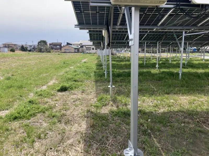
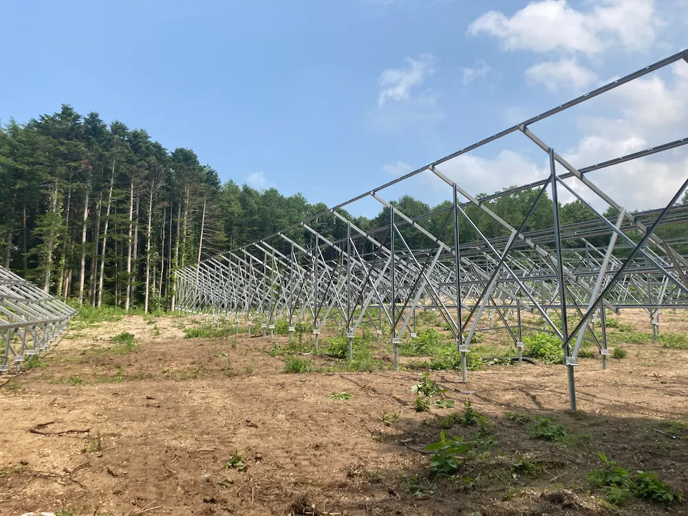
When designing utility-scale or large commercial solar arrays in river basins, coastal floodplains, or agricultural-solar (Agri-PV) co-location sites, elevating the lowest string of PV modules is an operational necessity. Keeping electrical components, trackers, and modules above historical flood crests avoids catastrophic component failure, string ground faults, and rapid back-sheet degradation. In this case, conventional ground-mounted platform installation is generally not used; instead, Elevated Ground Mounting Systems are selected.
However, from a structural engineering standpoint, lifting an array from a standard ground clearance of 0.5 meters to an elevated clearance of 2.0 to 3.5 meters completely rewrites the risk profile of the project. Every 10 centimeter of added height increases the structural vulnerability of the system to severe wind events.
2. The Mechanics of Elevation: Why Height Changes the Wind Load Game
Why does adding two meters of ground clearance complicate your structural calculations so drastically? It comes down to basic leverage and boundary layer fluid dynamics. Have your structural teams looked past the basic static wind charts?
The Amplification of Bending Moments
Think of your vertical foundation post as a giant lever arm. On a standard ground mount, the wind force hits the PV table close to the pivot point (the ground line). The bending moment—the rotational force trying to snap or bend the post at the soil boundary—is highly manageable.
When you elevate the lowest edge of that same PV table to three meters to clear high watermarks, the distance between the center of the wind force and the ground increases significantly. Because this relationship is linear regarding height, tripling your effective clearance height can triple the bending stress concentrated exactly where the post emerges from the dirt. If your procurement team specifies standard, off-the-shelf C-channels without a localized upgrade in steel thickness or flange geometry, the structural post will simply buckle under peak wind loads, dragging thousands of panels down with it.
Aerodynamic Lift and the Open-Underside Effect
Standard ground mounts benefit from a natural aerodynamic phenomenon: the ground blocks a significant portion of the airflow, forcing the wind to ride up and over the front edge of the tilted PV array.
When you lift the system high into the air, you create a massive open plenum underneath the modules. Wind now rushes underneath the table unimpeded. When wind hits the tilted underside of an elevated array, it creates a dual-threat aerodynamic profile:
- High localized positive pressure pushing up on the rear modules from underneath.
- Intense negative pressure (suction) rolling over the top edge of the front panels.
This structural squeezing effect generates immense uplift and downward forces simultaneously across different zones of the rack. If your engineering firm is treating this like a standard rooftop or low-lying ground project, they are fundamentally underestimating the localized wind forces.
Adhering to Rigorous Global Standards
Designing elevated structures requires strict compliance with international structural codes that specifically model wind boundary layers and terrain shielding factors. At SR Solar, our internal engineering workflows validate designs against two main structural pillars:
- AS/NZS 1170.2: This standard is crucial for assessing terrain categories and wind directionality factors. As a structure rises further from the ground, it escapes the natural friction provided by surface terrain (like bushes, fences, and small buildings) and enters a higher wind speed zone. Elevated systems must be calculated using these elevated wind velocity profiles.
- JIS C 8955: The definitive guide for solar array structural design. It provides comprehensive models for calculating wind forces acting on both the windward and leeward sides of open-canopy structures, forcing engineers to account for the massive uplift forces experienced by elevated arrays during typhoon-strength events.
3. Material Selection and Structural Typologies for High-Wind, Flood-Prone Sites
Selecting the right materials and framing geometry for an elevated solar array is a balance between yield strength, corrosion resistance, and installation speed on site.
Zinc-Aluminum-Magnesium (ZAM) vs. Hot-Dip Galvanized (HDG) vs. Aluminum
For high-clearance projects in water-heavy zones, material selection cannot be an afterthought. Let’s break down how the primary structural materials perform in these demanding environments:
- Aluminum Alloys (6005-T5 / 6063-T6): Aluminum is highly regarded for its excellent strength-to-weight ratio and natural resistance to atmospheric corrosion. However, for elevated structures dealing with immense bending moments, aluminum lacks the raw modulus of elasticity required to resist excessive deflection and swaying. To achieve the same structural rigidity as steel at a 3-meter height, aluminum profiles must become thick and bulky, quickly eroding any logistical or weight advantages.
- Hot-Dip Galvanized Steel (HDG): A time-tested industry workhorse. Coating structural carbon steel with a heavy layer of zinc (often exceeding 85 microns) provides deep corrosion protection. However, HDG requires post-fabrication dipping. If installation crews drill holes, cut profiles, or scratch the coating during field adjustments in a humid wetland, those points instantly become raw propagation zones for rust.
- Zinc-Aluminum-Magnesium (ZAM) Coated Steel: The modern gold standard for utility-scale flood zone projects. ZAM coatings offer superior localized corrosion resistance compared to traditional HDG, even in highly alkaline or acidic wet soils. Crucially, ZAM possesses a “self-healing” chemical property. When a profile is cut or scratched on site, the magnesium and zinc migrate across the exposed raw steel edge to form a protective zinc carbonate layer. This eliminates the dependency on field-applied cold-galvanized sprays and guarantees structural health for decades.
Structural Frameworks: Single-Post vs. Dual-Post (A-Frame) Typologies
The structural layout of your mounting racks plays a definitive role in how wind loads are transferred down into the earth.
A common EPC error is attempting to scale up standard single-post ground mount designs to high-clearance heights simply to reduce the total number of driven piles. While a single-post design functions efficiently at a 0.6-meter clearance, using it at a 2.5-meter clearance creates a highly vulnerable structural profile. The single central post must absorb all lateral wind shear, uplift, and torsional forces on its own, concentrating immense stress directly at the ground line. To make a single-post system safe at this height, the steel must be excessively thick, and the pile must be driven incredibly deep, driving up material costs.
Conversely, a Dual-Post or A-Frame Typology leverages the timeless engineering concept of triangulation. By utilizing a front vertical post and a rear angled post, lateral wind forces hitting the PV table are instantly converted into balanced axial forces—tension (pulling up) on one post and compression (pushing down) on the other. This completely eliminates pure bending moments at the ground line, allowing for lighter, more cost-effective steel profiles while providing vastly superior lateral rigidity and eliminating structural swaying during wind gusts.
4. The “Real-World” Layer: Geotechnical Realities and Field Failures
A major blind spot for many EPCs is conducting geotechnical site assessments and pull-out tests during the dry season, obtaining excellent soil values, and assuming those numbers remain constant throughout the year. In a flood-prone zone, this assumption can be a multi-million-dollar mistake.
Soil Saturation and the Collapse of Skin Friction
When monsoon rains arrive or a river breaches its banks, the water table rises to the surface, fully saturating the soil matrix. In sandy or clay-heavy soils, saturation leads to localized liquefaction and a dramatic drop in internal soil cohesion. The skin friction—the grip that the dirt maintains against the rough surface of your driven steel pile—can plunge by more than half when the soil transitions from dry to fully water-logged.
If your engineering team calculated your pile embedment depth based exclusively on dry-soil pull-out parameters, the structure may hold fine in October, but by the height of the wet season in July, a modest wind storm could easily pull the piles straight out of the muddy ground.
The Hidden Danger of Hydraulic Scour
It isn’t just standing water you have to worry about; it’s moving water. When floodwaters move across a solar site, they generate hydraulic scour. The current accelerates as it constricts between your rows of foundation piles, actively washing away the top layers of soil around the base of the posts.
If a severe flood washes away the top 40 centimeters of soil, your effective pile embedment depth is suddenly reduced by that exact amount. If that happens across an entire block of arrays, the overturning resistance of the system is severely compromised exactly when wind conditions are often at their worst.
Field-Proven Engineering Rules for EPCs
To mitigate these hidden geotechnical risks, SR Solar’s engineering field teams recommend implementing the following site-planning protocols:
- Saturated Geotechnical Testing: Never rely on dry soil data. Always require your geotechnical sub-contractors to pre-soak test pits or execute pull-out tests within simulated saturated soil conditions to determine worst-case skin friction coefficients.
- The Scour-Line Safety Buffer: When calculating the required driven depth of your piles, completely discount the top 50 centimeters of soil. Assume it will be washed away or entirely compromised during a peak flood event. If your engineering calculations indicate you need 2.5 meters of soil engagement, your actual driven depth must be at least 3.0 meters.
- Strategic Knee Bracing: High-clearance structures are prone to harmonic vortex shedding—where rhythmic wind gusts cause the structure to rock back and forth, slowly loosening the soil around the foundation. Integrating stiff knee braces between the main horizontal beams and the vertical posts raises the natural frequency of the structure, neutralizing wind-induced vibrations before they can loosen your piles.
5. Economic Impact: Connecting Structural Integrity to EPC Profitability and LCOE
Every extra kilogram of steel or additional centimeter of pile depth specified by an engineer directly impacts your EPC bidding margin. However, looking at procurement costs in isolation is a short-sighted approach that can ultimately destroy a project’s Levelized Cost of Energy (LCOE) and decimate your company’s reputation.
Civil Labor Costs vs. Structural Safety
When you choose an under-engineered racking system to save a few dollars per kilowatt upfront, you aren’t just taking on structural risk; you are often driving up field labor costs. Lean, single-post high-clearance structures require immense precision during ramming and often necessitate massive, heavy-duty pile-driving rigs that get bogged down and stuck in soft, wet soils.
By utilizing optimized dual-post configurations from SR Solar, the structural load is shared. This allows for lighter, more agile piling equipment to be deployed on site, accelerating installation velocity and keeping your civil labor crews moving forward even in challenging soil conditions.
The Real Cost of Structural Failures
If an elevated array fails during a monsoon event due to inadequate wind or geotechnical engineering, the financial fallout goes far beyond replacing bent steel:
- Asset Write-Offs: When a rack twists or collapses, the localized bending forces crack the silicon cells inside the PV modules (micro-cracking), instantly voiding the module manufacturer’s warranty and rendering the panels useless.
- Insurance Disasters: Insurance underwriters are increasingly analyzing solar structural engineering blueprints post-loss. If they discover that the EPC utilized generic ground mount wind calculations for a high-clearance floodplain project without adjusting for the open-underside effect, the claim can be denied based on professional negligence.
- Post-Disaster Logistics: Repairing a collapsed solar field that is sitting in active floodwater or deep mud is an operational nightmare. The labor hours required to manually cut apart twisted steel, extract failed piles, and re-drive foundations in ruined soil are triple the cost of executing the installation correctly the first time.
6. Summary: Smart Engineering Protects Low-Margin Projects
Elevating ground mounts in flood-prone regions is a complex structural balancing act. You cannot simply take a standard ground mount, weld longer legs onto it, and hope for the best. Increasing the clearance height drastically multiplies wind shear and uplift forces, while concurrently, seasonal floodwaters compromise the very soil holding your foundations in place.
To ensure long-term project survival, EPCs must treat high-clearance systems as specialized structural canopies. By executing saturated soil testing, accounting for hydraulic scour, moving to triangulated dual-post framing layouts, and specifying self-healing materials like ZAM steel, contractors can deliver resilient solar assets that safeguard investor capital and preserve thin EPC delivery margins over the long term.
FAQs (Frequently Asked Questions)
Q1: How do you determine the correct pile embedment depth for an elevated solar array in a known wetland?
The target embedment depth is calculated by combining your peak wind uplift forces (derived using wind code multipliers for the specific array height) with the reduced skin friction value of the soil under fully saturated conditions. Additionally, engineers must subtract the top layer of soil susceptible to hydraulic scour from their calculations. Consequently, elevated ground mounts often require an embedment depth that is 30% to 50% deeper than standard ground arrays on firm terrain.
Q2: Is it feasible to use single-axis trackers for high-clearance, flood-prone solar projects?
While single-axis trackers maximize daily energy yield, elevating them to high clearances introduces substantial structural risks. The main torque tube must handle immense torsional (twisting) loads when elevated wind forces rush underneath the moving modules. For high-clearance flood zones, fixed-tilt structures are heavily favored because their interconnected bracing networks provide vastly superior structural rigidity and eliminate mechanical failure points.
Q3: Why is Zinc-Aluminum-Magnesium (ZAM) steel superior to Hot-Dip Galvanized (HDG) steel for seasonal flood plains?
While both provide excellent rust prevention, HDG relies on a static layer of zinc that can crack or flake if the structural steel flexes under extreme wind loads, or if it is scratched during rough site installation. ZAM steel features an advanced alloy coating that chemically reacts with moisture to form a self-healing protective layer over exposed cut edges and drill holes, ensuring long-term structural health even when periodically submerged in muddy floodwaters.
Q4: How do you prevent wind vortex shedding from loosening driven piles in soft, wet soils over time?
Wind blowing across a high-clearance solar table creates alternating low-pressure vortices behind the structure. This phenomenon, known as vortex shedding, causes the array to experience micro-vibrations or rhythmic rocking. Over a period of months, this motion can wallow out the soil surrounding the top of the foundation pile. Incorporating heavy-duty knee bracing and cross-bracing dampens these vibrations, transferring the forces evenly across the entire structural network and protecting the integrity of the soil-to-pile interface.
Q5: Can concrete ballasts or collars be used if the soil is too soft for standard driven piles?
Absolutely. In areas with deep alluvial mud where driven steel piles cannot achieve adequate friction values, pre-cast concrete block foundations or cast-in-situ concrete piles with enlarged bases are highly effective. These engineering alternatives rely on pure gravity mass and mechanical anchoring rather than soil friction to counteract the immense uplift forces acting on the elevated solar tables.
Planning an elevated solar project in a challenging terrain? Don’t rely on guesswork when it comes to complex wind load distributions and saturated soil dynamics. Contact the SR Solar engineering team today to receive a comprehensive geotechnical analysis and a custom-engineered racking blueprint designed for your project’s exact environmental constraints.