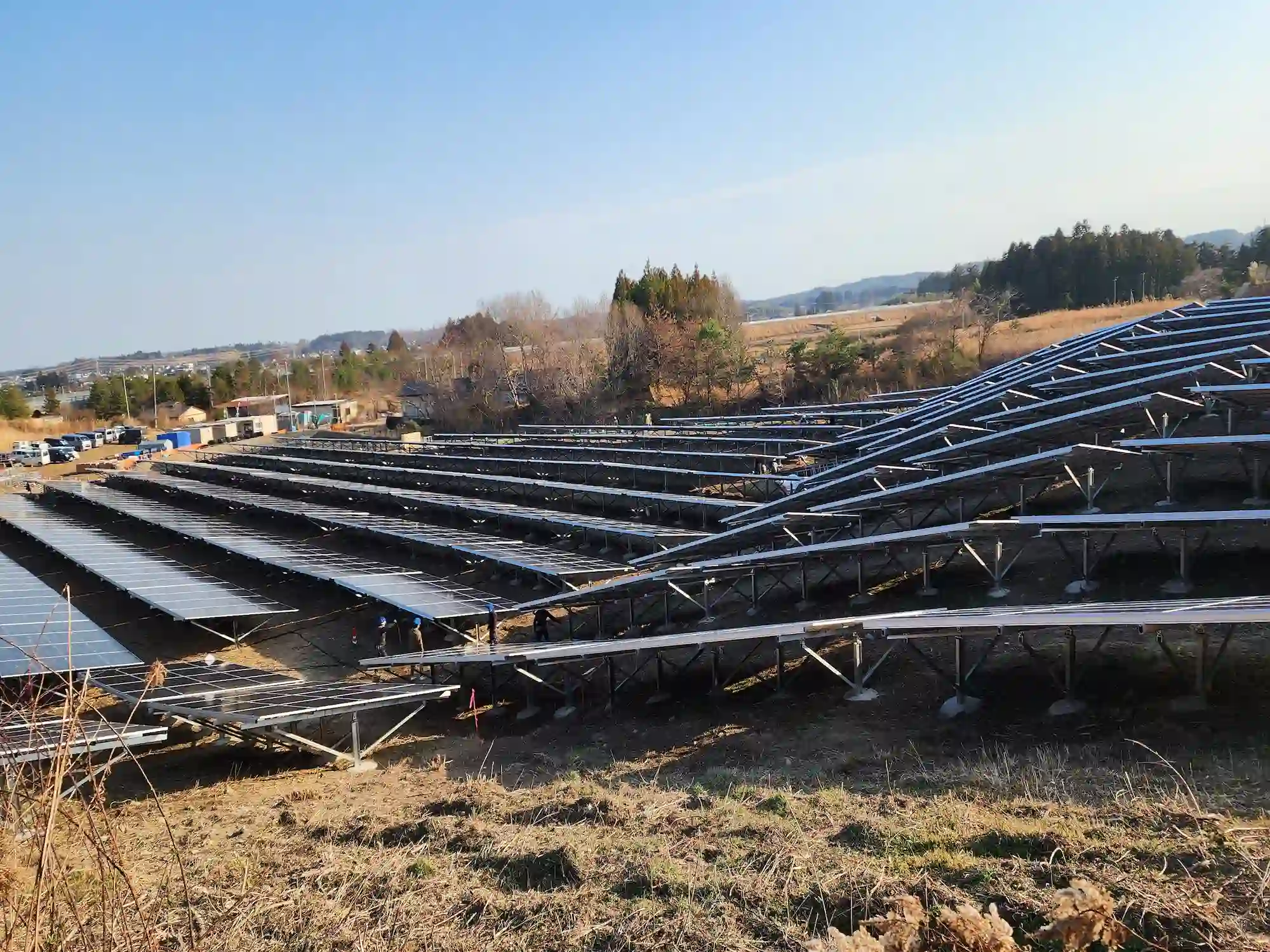
When engineering a utility-scale asset, many Engineering, Procurement, and Construction (EPC) contractors mistakenly focus their structural risk assessments on wind loads and module layouts. But where does the structural integrity of a utility-scale solar plant actually fail? It fails beneath the surface. Selecting the wrong foundation for a utility-scale ground mounting system because of incomplete subsurface analysis is one of the fastest paths to project delays, structural failures, and exponential Levelized Cost of Electricity (LCOE) inflation. Surface topography is highly deceptive. What looks like a perfectly flat, uniform pasture can conceal erratic strata, subterranean bedrock, highly corrosive soils, or non-cohesive sand layers that compromise your structural calculations. To mitigate risk and ensure a 25-to-30-year operational lifetime, every structural engineering decision for a utility-scale ground mounting system must be dictated by comprehensive geotechnical data.
1. The Decision-Oriented Framework: Subsurface Conditions vs. Foundation Choices
How do you navigate the complex trade-offs between soil mechanics, mechanical load handling, and execution efficiency? EPCs cannot afford to guess. The following engineering matrix maps specific subsurface conditions directly to optimized foundation selections for a high-performance ground mounting system, evaluating structural performance alongside real-world civil constraints.
| Subsurface / Soil Classification | Recommended Foundation for Ground Mounting System | Primary Mechanical Standard / Limit State | On-Site Labor & Equipment Implications | LCOE & CAPEX Risk Level |
| Cohesive Clays & Loose Silts (Soft to Medium stiff) | Driven Piles (Steel H-Beams or C-Channels) | ASTM D1143 (Axial Compression) ASTM D3689 (Axial Tension/Uplift) | High-speed hydraulic ramming. Minimal on-site crew size. Eliminates curing periods. | Low CAPEX. High efficiency if minimum embedment depth is accurately calculated. |
| Highly Variable Strata & Rocky Slopes (Mixed cobbles, dense gravels) | Continuous Flanged Ground Screws | IBC Chapter 18 / ISO 1461 High torsion & pull-out resistance | Requires specialized rotary drilling rigs. Higher initial tooling cost but eliminates pre-drilling. | Medium CAPEX. Highly predictable execution in challenging topography. |
| Solid Bedrock & Caliche Layers (Shallow rock depths less than 800 mm) | Pre-Drilled Piles with Micro-Concrete Grouting | Eurocode 3 & 2 (Steel & Concrete) Rock-to-steel bond stress limit | Heavy down-the-hole (DTH) hammer rigs required. Multi-stage process: drill, place, grout. | High CAPEX. Drastically increases installation time per megawatt. |
| Environmental Brownfields / Landfills (In-situ penetration prohibited) | Ballasted Concrete Strip Foundations | AS/NZS 1170.2 (Overturning) JIS C 8955 (Sliding resistance) | Heavy logistics for precast or massive batching plants for cast-in-place. Extreme labor load. | Maximum CAPEX. Used only when subsurface penetration is legally or physically impossible. |
2. Deep Foundation Mechanics and Structural Material Selection
A high-performance ground mounting system relies entirely on the underground foundation to resist heavy environmental forces. To withstand these static and dynamic loads over decades, the structural choice of the foundation type and its steel chemical composition must match the project site exactly.
Driven Steel Piles: High-Volume Production in Cohesive Soils
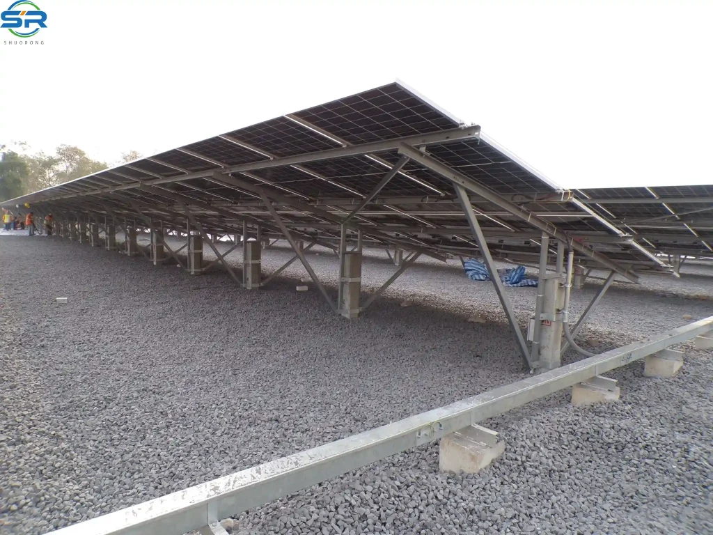
Driven steel piles, typically in the form of C-channels, H-beams, or U profiles, represent the most common foundation for large utility projects. This foundation type works by mobilizing the skin friction between the driven steel surface and the surrounding soil strata, as well as the end-bearing capacity at the pile tip. Structural carbon steel, such as Q355B, is used due to its high yield strength (greater than or equal to 355 MPa) and superior stiffness, which prevents the steel post from buckling while being hammered deep into the earth.
To combat the corrosive nature of underground moisture and soil chemistry, modern foundations increasingly utilize Zinc-Aluminum-Magnesium (ZAM) steel coatings instead of traditional hot-dip galvanizing. The magnesium in a ZAM-coated ground mounting system foundation reacts with atmospheric and soil moisture to form a protective layer of zinc hydroxychloride. This layer provides a self-healing mechanism that covers sheared edges or minor scratches caused by rocks during the driving process, ensuring long-term structural thickness below grade.
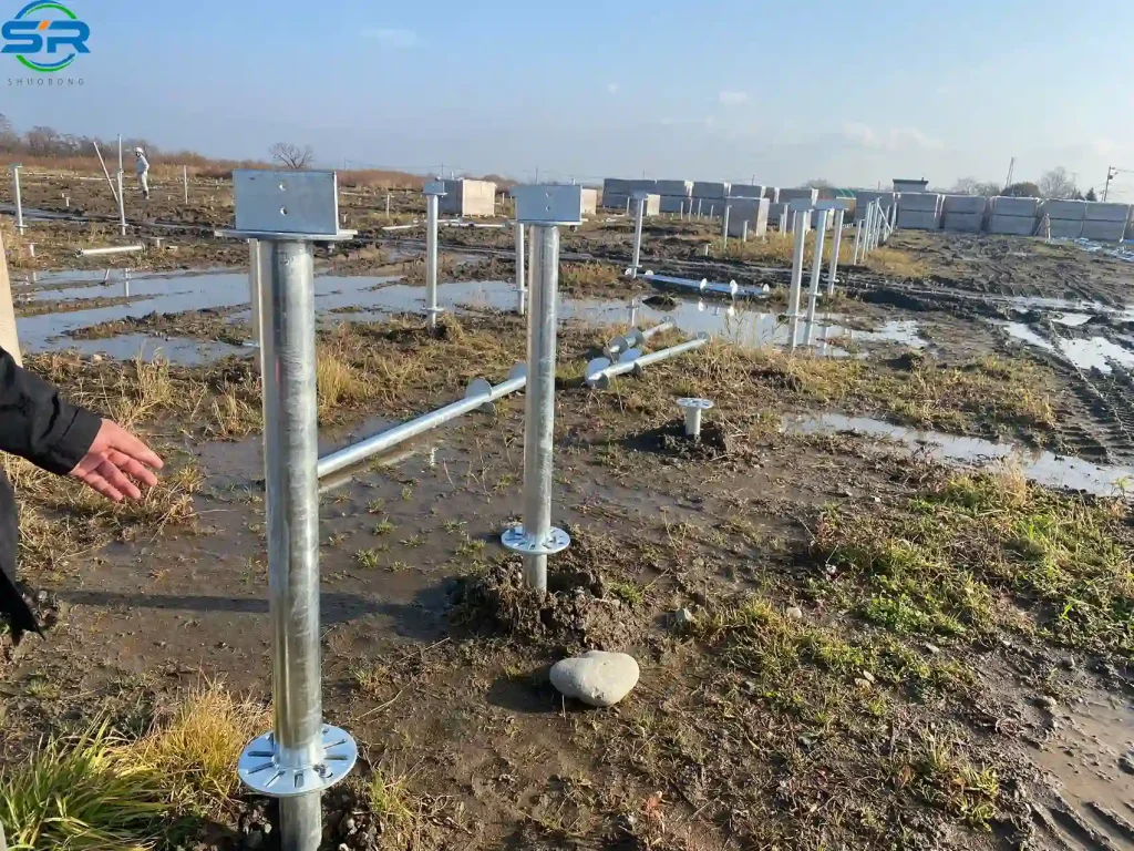
Ground Screws: Mechanical Anchoring in Challenging Strata
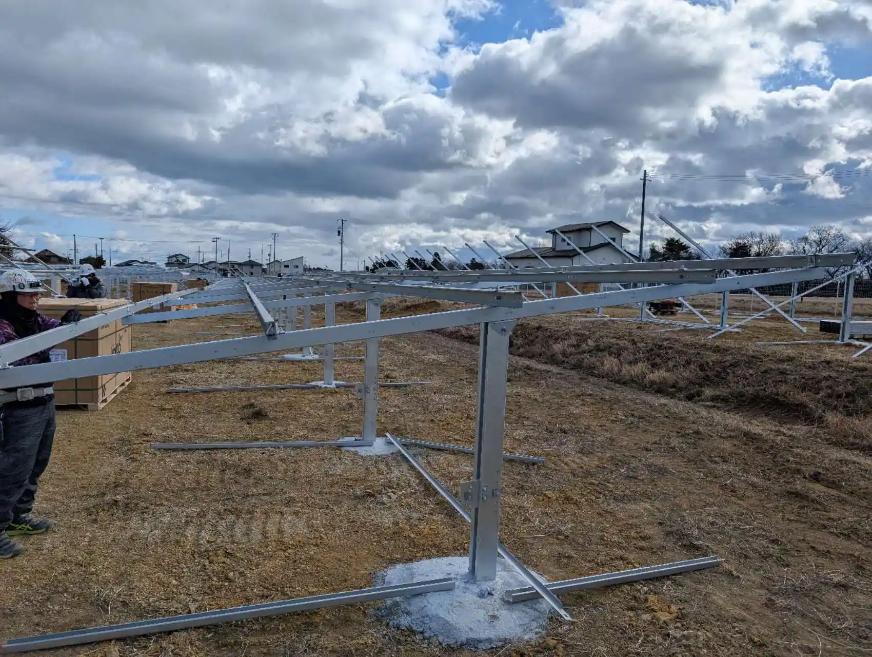
When the underground profile contains dense gravel, variable cobbles, or non-cohesive sandy silt, smooth driven piles often fail to achieve the required pull-out resistance. In these geotechnically challenging zones, continuous flanged ground screws provide a far safer engineering alternative for a ground mounting system.
Ground screws function as mechanical anchors. The helical steel threads cut directly into the soil layers, compacting the earth immediately surrounding the pipe shaft during installation. This compaction creates a localized zone of high density, allowing the foundation to utilize the dead weight of the surrounding inverted soil cone to resist massive wind uplift forces. Ground screws are typically manufactured from robust steel tubing with high torsion resistance, ensuring the foundation can withstand the high torque applied by rotary drilling rigs without twisting or tearing the steel.
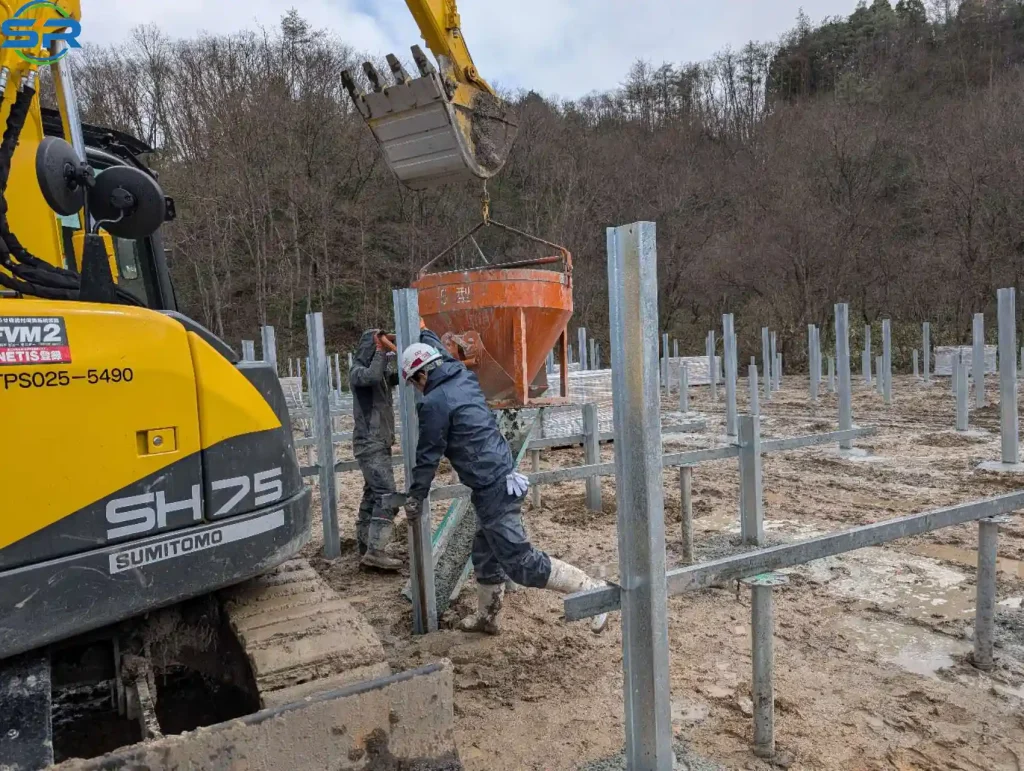
Concrete Ballast and Pre-Drilled Grout Piles: Solutions for Extreme Subsurface Rigidities
In areas where solid bedrock or thick caliche layers sit close to the surface (less than 800 mm deep), standard driven piles cannot penetrate, and ground screws cannot cut through the rock. The engineering team must then pivot to pre-drilled grout piles or concrete ballasted bases.
Pre-drilled systems use heavy pneumatic hammer drills to create a pilot hole through the rock layer, after which a steel post is inserted and secured with a high-strength concrete grout mix. This creates a rock-to-steel bond stress limit capable of handling severe structural loads. If the site is an environmental landfill or brownfield where breaking the subterranean containment membrane is completely prohibited, a ballasted concrete strip foundation becomes the only viable choice for the ground mounting system. These massive concrete blocks rely entirely on dead weight and the sliding friction coefficient between the concrete and the surface to keep the structural asset secure against overturning moments.
3. The “Real-World” Engineering Layer: Geotechnical Failures and Field Adjustments
In our extensive project experience at SR Solar, we frequently observe a common EPC error: assuming that a foundation type chosen based on a few initial soil borings will work across the entire project layout. Soil profiles change dramatically across expansive utility sites, and failing to adjust the foundation type can lead to catastrophic schedule overruns.
Field Case Study: The Cost of Overlooking Subsurface Foundation Changes
During the execution of a 4.5MW utility project in a semi-arid valley region, the EPC carried out localized pull-out tests at just three convenient roadside access points. The initial geotechnical report suggested uniform, stiff clay down to a depth of 2.5 meters. Based on this data, the EPC specified standard driven C-channel steel piles for the entire ground mounting system foundation layout, targeting an embedment depth of 1800 mm.
However, when the heavy hydraulic ramming rigs began work in the central and northern zones of the site, they encountered an unmapped subterranean caliche layer (a hardened natural cement layer of calcium carbonate) at depths ranging from 600 mm to 900 mm. Attempting to force the driven piles through this rigid layer resulted in widespread pile deformation, severe buckling of the steel flanges, and structural damage that stripped the protective ZAM coatings from the steel surfaces. Pile rejection rates climbed rapidly to 34% in the affected zones, completely stalling the project schedule.
Remediation Strategy and Foundation Adjustment
To keep the project on track, their engineering team immediately modified the foundation deployment layout. We implemented a two-fold engineering remediation strategy:
- Where the caliche layer measured thicker than 300 mm, they brought in down-the-hole (DTH) pneumatic hammer drills to create a 50 mm pilot hole, allowing the driven steel piles to pierce the hard layer without structural buckling or losing their protective coatings.
- In areas where the caliche layer transitioned into shallow, non-cohesive sandy silt with poor lateral stability, they quickly pivoted from driven piles to continuous-thread ground screws. The helical threads provided the necessary mechanical interlock with the sandy soil, generating the required pull-out resistance without requiring deep embedment.
What is the key lesson here for utility-scale EPCs? Never assume uniform subsurface conditions. A comprehensive geotechnical profile—incorporating regular borehole testing every 250 to 300 meters across your entire site footprint—is essential to protect your project budget and maintain your installation timeline.
4. Economic Impact Analysis: Foundation Decisions Driving LCOE
Engineering choices regarding foundation selection directly shape project economics. Every structural optimization made to the underground portion of a utility-scale ground mounting system influences your CAPEX, on-site labor requirements, and long-term project LCOE.
Balancing Foundation Material Volume and Civil Installation Costs
A common engineering dilemma is choosing whether to increase the material volume of the foundation (such as using longer, heavier driven steel posts) or to increase the complexity of the installation process (such as pre-drilling or adding concrete).
Optimizing the foundation framework to be as material-efficient as possible reduces your upfront steel CAPEX. However, this means the foundation must achieve maximum performance through raw depth, demanding deeper pile embedment or larger ground screw diameters to resist equivalent uplift forces. The optimal solution requires evaluating local steel pricing against the cost of running on-site civil piling crews and heavy drilling machinery to find the most cost-effective balance for the ground mounting system.
Quantifying Civil Labor Dynamics and Installation Times
On-site civil labor costs often outweigh material cost differences. The table below illustrates the real-world installation metrics for a standard 1MW solar array table using three different foundation typologies for a commercial ground mounting system.
| Foundation Typology | Average Piles / Screws per MW | Installation Rate (Units / Hour / Rig) | Total Labor Hours per MW (Crew of 4) | Sensitivity to Changing Weather Conditions |
| Direct Driven Steel Piles | 360 to 420 | 12 to 15 piles per hour | 96 to 112 hours | Low. Operations can continue in wet, frozen, or muddy ground conditions. |
| Continuous Ground Screws | 340 to 390 | 8 to 10 screws per hour | 136 to 156 hours | Medium. High mud content can reduce traction for heavy rotary drilling machinery. |
| Pre-Drilled + Grout Piles | 360 to 420 | 3 to 5 units per hour | 288 to 336 hours | High. Rain or freezing weather disrupts concrete mixing, placing, and curing schedules. |
As the data clearly demonstrates, choosing direct driven steel piles can reduce your structural labor requirements by up to 60% compared to pre-drilled grouted systems. However, this high production rate is only achievable if your subsurface geotechnical data confirms that the soil is free of dense rock formations that would block the piling rigs.
5. SR Solar Integration: Authoritative Foundation Engineering Standards
At SR Solar, we do not view structural design as a standard, one-size-fits-all manufacturing process. Every utility-scale ground mounting system foundation we supply undergoes custom engineering validation overseen by our experienced structural engineering team. We utilize specialized software to model real-world soil-structure interaction, verifying load-bearing capabilities, axial tension resistance, and structural safety before any components are manufactured.
By matching the exact metallurgy of our steel driven piles and helical ground screws to the corrosion and density profile of your site, our foundation choices are optimized to minimize structural risk. This rigorous design and quality control workflow minimizes field modifications, accelerates on-site civil installation timelines, and lowers structural risks for utility-scale EPC contractors and developers worldwide.
6. Conclusion and Strategic Engineering Summary
In utility-scale solar asset design, the foundation is the structural link between your multi-million dollar solar modules and the earth. Choosing foundation components for a ground mounting system based on surface visuals rather than thorough geotechnical data is a major project risk. For a project to hit its commissioning deadlines and achieve its financial targets, your subsurface foundation parameters must be fully validated before ordering components or deploying civil construction crews.
Frequently Asked Questions (FAQs)
Q1: Can a driven steel pile foundation be used on a site with a 15-degree slope?
Yes, but it requires adjusting your foundation calculations. When installing a ground mounting system foundation on a slope, the effective embedment depth must be measured from the down-slope side of the pile to account for reduced lateral soil resistance. You must also adjust the stroke height of your hydraulic ramming rigs to ensure the posts remain perfectly vertical across the changing terrain.
Q2: How do corrosive soils (high chlorides or low pH) affect the choice of foundation?
Highly corrosive soils accelerate the degradation of underground structural steel. If your geotechnical chemistry report shows a pH below 5.0 or chloride levels above 200 ppm, traditional hot-dip galvanized steel foundations may fail prematurely. For these conditions, we recommend using ZAM-coated steel profiles or adding sacrificial steel thickness to the bottom of the piles to ensure structural stability over a 25-year lifespan.
Q3: What is the minimum required pull-out resistance for a standard utility-scale foundation?
The required pull-out resistance depends entirely on your local design wind speed and the total surface area of your solar tables. For example, under AS/NZS 1170.2 wind parameters, a standard utility solar foundation often requires an ultimate uplift resistance of 25 kN to 35 kN per pile. This must be verified on-site through systematic static pull-out testing.
Q4: How do ground screws maintain high pull-out resistance in loose, sandy soils?
Ground screws generate high pull-out resistance by compacting the soil surrounding the screw during installation. The wide helical threads cut smoothly into the ground and lock into the soil structure, utilizing the weight of the surrounding soil cone to resist uplift forces much more effectively than smooth-sided driven posts.
Q5: When should an EPC choose concrete ballasted bases instead of driven steel piles or ground screws?
Concrete ballast blocks should be used when the subsurface cannot be disturbed or penetrated. Typical examples include capped environmental landfills, rocky conservation zones, or urban brownfield sites with shallow buried infrastructure. Because ballasted systems rely entirely on friction and dead weight to resist wind loads, they require flat ground and incur higher material and logistics costs.
Request a Technical Engineering Consultation > Are you currently engineering a utility-scale solar asset with challenging ground conditions or strict regional structural codes? Contact the SR Solar engineering division today. Our structural specialists will review your geotechnical reports, perform custom load calculations, and help design a dependable, site-optimized foundation strategy for your upcoming project.