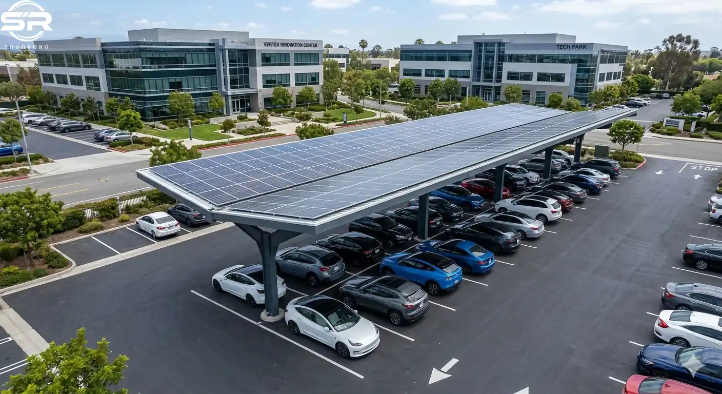
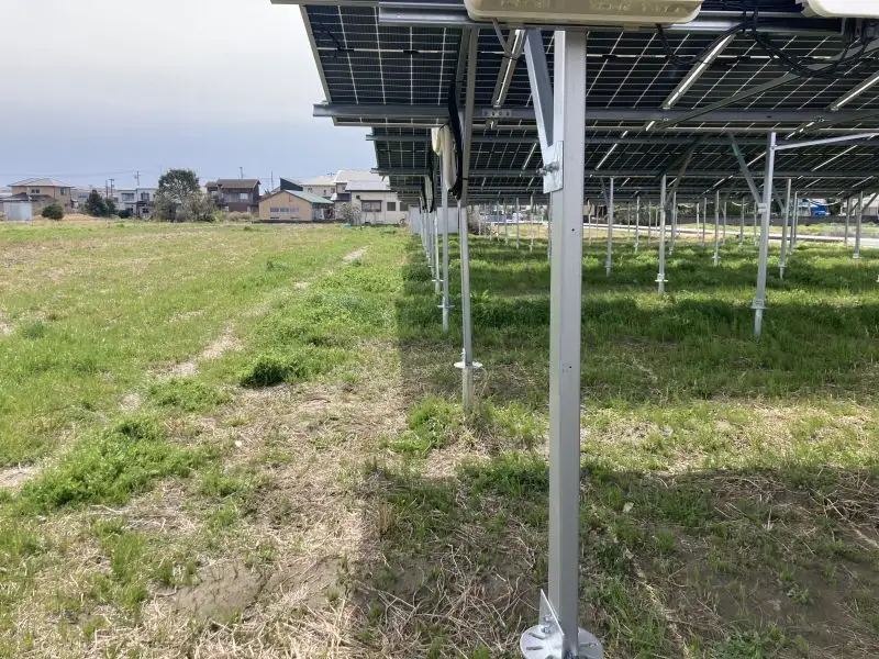
Land scarcity is the primary bottleneck for utility-scale solar development. For Engineering, Procurement, and Construction (EPC) contractors, securing flat terrestrial acreage involves high civil grading costs and regulatory friction. This constraint has accelerated the deployment of water-based arrays, specifically fishery-solar hybrid systems (aquaculture-solar PV).
But how do you stabilize thousands of solar modules over a dynamic, high-humidity, chemically active water surface for 25 years without structural deformation?
1. The Fishery-Solar Integration: Thermodynamic & Biological Realities
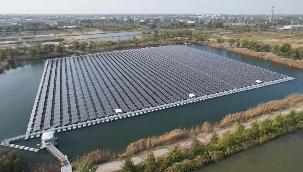
A fishery-solar hybrid system co-locates photovoltaic generation with commercial aquaculture. This configuration triggers a distinct thermodynamic loop that directly alters project economics.
The Water Cooling Effect
Solar modules suffer from a negative temperature coefficient: as ambient temperatures spike, electrical efficiency drops. Water bodies provide natural evaporative cooling. The microclimate beneath a floating array lowers operational module temperatures compared to ground-mount installations, yielding more annual energy production (AEP) premium.
Aquaculture Impact
The floating structure acts as a physical canopy over the water.
- Algal Suppression: By blocking photosynthetic active radiation, the system reduces harmful algal blooms, preserving dissolved oxygen for aquatic livestock.
- Water Preservation: The canopy curtails evaporation losses, stabilizing salinity levels in managed fish and shrimp ponds during dry seasons.
2. Decoupling the Mechanics: Component Breakdown
What is a floating PV mounting system mechanically? It is a structural matrix that replaces traditional driven steel piles or concrete foundations with hydrostatic buoyancy, utilizing a specialized mooring network to counter lateral environmental forces.
An industrial-grade floating system contains three core subsystems:
A. Polymeric Buoyancy Elements (Floats)
Hollow, thin-walled structures manufactured via blow molding or rotational molding.
- Main Floats: Positioned directly beneath the solar modules, sloped to dictate the system tilt.
- Walkway/Aisle Floats: Positioned between rows to allow maintenance access while acting as localized torsional stabilizers across the array.
B. Structural Superstructure (Racking)
The metal framing matrix that bridges the flexible polymer floats to the rigid glass solar modules. It isolates the modules from the twisting, multi-axis forces generated by wave movement, preventing micro-cracking in the silicon cells.
C. Anchoring & Mooring Grid
The connection mechanism binding the dynamic floating matrix to the topography of the site. It uses underwater concrete deadweights, shoreline anchor blocks, or driven land piles combined with high-tensile polyester ropes or galvanized steel chains to absorb kinetic kinetic energy from wind and currents.
3. Site Condition Analysis: Environmental Loading Criteria
Applying standard terrestrial structural design codes to water environments is a high-risk error. Engineers must map three critical site vectors before finalizing structural calculations.
Wind Shear Boundary Layers
Open water features minimal surface roughness. Without trees or terrain to disrupt air masses, wind accelerates rapidly across reservoirs.
Design calculations must use open-water exposure parameters (such as Category D in ASCE 7). Because a floating array forms a continuous low-profile airfoil, wind passing over the structure creates intense aerodynamic uplift on rear rows and extreme downward downward forces on leading edges. To minimize this sail effect, floating system tilt angles must be restricted.
Hydrodynamic Loading
- Significant Wave Height: Generated by wind fetch (uninterrupted travel distance over water). Waves exceeding 0.5 meters induce continuous cyclic bending stresses across structural junctions.
- Current Velocity: Flowing water creates continuous hydrodynamic drag against the submerged profiles of the main floats, compounding tension on anchor lines.
Bathymetry & Drawdown Volatility
Hydroelectric reservoirs or managed agricultural basins often exhibit seasonal water fluctuations exceeding 10 meters.
- The Drawdown Threat: If the water table drops below minimum depth, the array will ground out on the bed. If the bed is rocky or uneven, concentrated point loads will puncture polymer floats.
- Line Slack: Drastic water level changes require self-adjusting or highly calculated mooring angles to prevent lines from going completely slack (causing array drifting) or over-tensioning (causing anchor failure).
4. Material Science in Highly Corrosive Microclimates
Fishery-solar environments feature 100% relative humidity paired with gaseous ammonia and hydrogen sulfide from biological decomposition. Standard terrestrial steel specifications fail rapidly here.
Polymeric Specifications (HDPE)
Pontoons must be engineered from 100% virgin High-Density Polyethylene (HDPE).
A Common EPC Error: Specifying low-cost floats containing recycled post-consumer plastics. Recycled resins degrade under continuous UV exposure and cyclic mechanical flexing, leading to rapid Environmental Stress Cracking (ESC) and water ingress.
Metallurgical Engineering (ZAM & Aluminum)
- Zinc-Aluminum-Magnesium (ZAM): Used for primary load-bearing structural rails. ZAM offers up to ten times the corrosion resistance of traditional hot-dip galvanized steel in high-ammonia environments. It features self-healing cut edges; the magnesium reacts with atmospheric moisture to form a dense protective film over exposed steel cuts.
- Anodized Aluminum (Al6005-T5): Used for module clamps and lightweight purlins. Must feature a minimum 15-micron anodizing film layer to resist pitting.
- Fasteners (SUS316): All structural bolts and pins must be marine-grade stainless steel to prevent localized thread stripping under stress.
5. Structural Typologies: True Floating vs. Fixed-Pile
EPCs must evaluate two distinct structural executions for aquaculture applications:
True Floating Systems (Buoyancy-Driven)
The complete structure rests dynamically on the water surface, moving in synchronization with wave vectors.
- Mooring Execution: Secured via bottom-sunk concrete blocks or bank anchors linked to flexible lines.
- Application Profile: Ideal for deep waters, shifting water levels, and sites with unknown or soft soil profiles where underwater piling is economically unfeasible.
Fixed-Pile Over-Water Systems
A traditional ground-mount framework elevated on extended concrete or steel piles driven directly into the reservoir floor.
- Mooring Execution: No floats or mooring lines; loads transfer directly into the subsoil via rigid vertical members.
- Application Profile: Restrained to shallow profiles, high-velocity river channels, or aquaculture systems requiring deep vertical clearance for heavy netting machinery.
Comparative Engineering Matrix
| Engineering Metric | True Floating System (HDPE) | Fixed-Pile Over-Water System |
| Water Depth Limit | Virtually unlimited | Constrained to under 3.5m due to pile buckling risks |
| Geotechnical Risk | Low; anchor blocks rest on the soil surface | High; demands intensive underwater soil boring tests |
| Primary Stress Vector | Cyclic fatigue, joint shear, tensile line pull | Bending moments on long unbraced pile lengths |
| Installation Logistics | Low-to-moderate; onshore assembly, modular launch | High; requires specialized marine pile-driving barges |
| Thermal Efficiency Benefit | Maximum; direct contact with water boundary layer | Moderate; large air gap reduces evaporative cooling |
Request a Technical Engineering Consultation
Optimizing a utility-scale fishery-solar project requires a precise balance between structural mass and localized wind/wave simulations. Contact the SR Solar engineering team today for a comprehensive site assessment, wind-load analysis, and tailored anchoring configuration.
Frequently Asked Questions
Q1: How do floating systems handle ice sheet formation?
Standard HDPE pontoons feature sloped hulls. When water freezes into sheet ice, the lateral pressure squeezes the elastic hull upward rather than crushing it. However, if the site experiences dynamic shifting ice (ice shoves), a true floating matrix will fail; a fixed-pile system or a pre-winter water drawdown is mandatory.
Q2: How do you adjust for mooring line stretch and creep over time?
Synthetic ropes (nylon/polyester) suffer from permanent elongation (plastic creep) over extended operational periods. SR Solar anchoring configurations utilize inline tension-limiting springs or shore-based winch blocks, allowing O&M crews to recalibrate line tension from land during annual checkups without requiring commercial divers.
Q3: What is the maximum rated wind survival capacity?
When deployed at a low tilt profile (5 to 7 degrees) paired with optimized concrete deadweight sizing, an SR Solar engineered system can survive wind velocities up to 50 m/s (180 km/h), equivalent to Category 3 hurricane forces.
Q4: Can these freshwater designs be deployed offshore in ocean waters?
No. Open ocean deployments expose structures to significant wave heights exceeding 2.0 meters paired with high salinity. Standard modular HDPE pontoons lack the structural rigidity required. Offshore systems demand marine-grade aluminum alloys, thick hot-dip galvanization exceeding 100 microns, or heavy semi-submersible elastomeric composite platforms.
Q5: How is electrical grounding executed across non-conductive HDPE floats?
Because HDPE is an electrical insulator, a continuous grounding path cannot be achieved through the floats. Specialized copper grounding clips must bridge the aluminum module frames to the metal superstructure racking on every row. These rows terminate into heavy-duty, marine-grade flexible copper grounding conductors that follow the mooring lines to a certified terrestrial grounding grid on the shore.